

Overview
Having a pet is like having another person that is dependent on the owner. Many of us are too busy that sometimes we forget to feed our pets and leave them hungry. This project allows us to build a pet feeder when it detects motions. It will also show a countdown and captures an image of the pet when it is feeding.
This project uses ESP32-CAM to capture an image when the PIR sensor detects motion. When motion is detected, the display module (LCD module for version 1 and OLED module for version 2) will display a cooldown timer and activates the Servo motor to open the pet food container and close it afterwards.
We have created two versions of the project so that pet owners will know which one they would like the best:
Version 1: Pet Feeder with LCD Countdown using ESP32-CAM
This version uses a 16x2 LCD Module to display the text that motion has been detected and the servo dispenses the pet food for 3 seconds.
Version 2: Pet Feeder with OLED Countdown using ESP32-CAM and ESP32
This is a refined version of the version 1 but instead of the LCD module, we used OLED display and added an image capturing so that owners will gets a picture of their pet eating. This version also used two microcontrollers; ESP32-CAM to control the PIR sensor and to snap the picture, and the ESP32 to control the servo motor and OLED display.
Hardware Components
-
ESP32-CAM
- MG996R Servo Motor
- Jumper Wires
- Breadboard
- LCD Module - Version 1
- Mini PIR Sensor - Version 1
- ESP32 - Version 2
- PIR Sensor - Version 2
- OLED Module - Version 2
Software Used
- Arduino IDE
Application Discussion
ESP32-CAM 
ESP32-CAM is a small size camera development board based on ESP32, set WIFI+ Bluetooth solution in one body, the development board can work independently as a minimum system. and is perfect for IoT devices requiring a camera with advanced functions like image tracking and recognition.
Specifications
Core:
- Microcontroller: ESP32-D0WDQ6
- CPU: Dual-core 32-bit Xtensa® LX6 @ up to 240 MHz
- RAM: 520 KB SRAM + 8 MB PSRAM
- Flash Memory: 4 MB
Connectivity:
- Wi-Fi: 802.11 b/g/n
- Bluetooth: v4.2 BR/EDR + BLE
Camera (OV2640):
- Resolution: Up to 1600x1200 (UXGA)
- Output Formats: JPEG, BMP, Grayscale
- Focus: Fixed focus
- FOV: ~65°
Storage:
- MicroSD slot: Supports up to 4–8 GB (FAT32)
- Image Storage: Saves captured photos in JPEG format
Power:
- Input Voltage: 5 V (via 5V pin)
- Operating Voltage: 3.3 V internally
- Typical Current Usage: ~160–250 mA during Wi-Fi + camera use
I/O and Interfaces:
- Usable GPIOs: 9 (shared with camera functions)
- Interfaces Supported: UART, SPI, I2C, PWM, ADC
- Built-in Flash LED: White (connected to GPIO 4)
Physical:
- Dimensions: ~27 mm × 40.5 mm
- Antenna Options: Onboard PCB + U.FL connector for external antenna
Pinout:
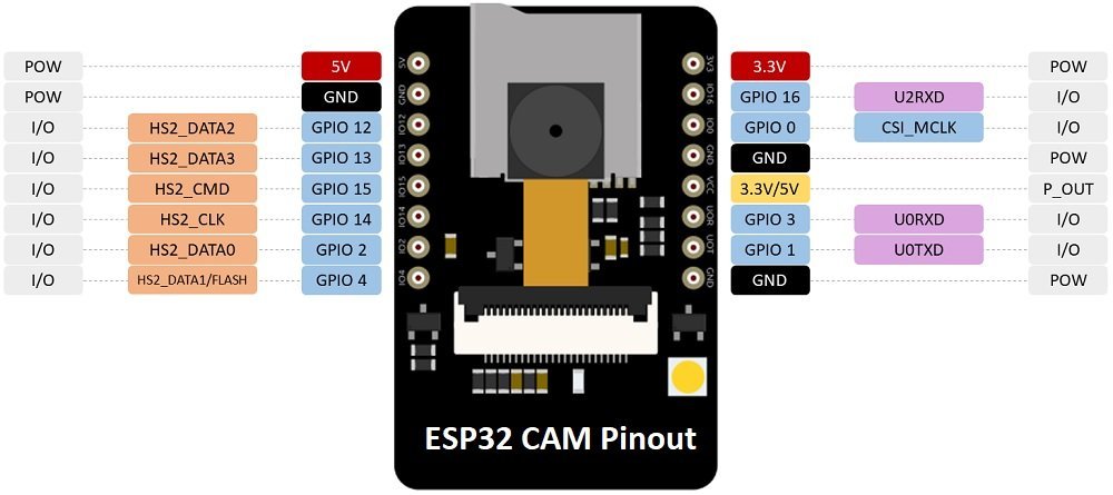
To upload code using ESP32-CAM:

The MG996R is a strong, reliable servo motor that’s perfect for projects like robot arms, RC cars, or anything that needs precise and powerful movement. It runs on 4.8 to 7.2 volts and uses standard PWM signals, making it easy to control with most microcontrollers like Arduino or ESP32. Thanks to its metal gears and high torque, it can handle heavier loads without losing accuracy or speed.
Specifications:
- Operating voltage: 4.8V to 7.2V
- Stall torque: 9.4 kg·cm (4.8V), 11 kg·cm (6V)
- Speed: 0.20 sec/60° (4.8V), 0.16 sec/60° (6V)
- Rotation range: 0° to ~180°
- Gear type: Metal
- Dimensions: 40.7 x 19.7 x 42.9 mm
- Weight: ~55g
- Signal control: PWM (500–2500 µs pulse width)
- Bearing type: Dual ball bearings
Wire Configuration
|
Wire Number |
Wire Color |
Description |
|
1 |
Brown |
Ground wire connected to the ground of system |
|
2 |
Red |
Powers the motor typically +5V is used |
|
3 |
Orange |
PWM signal is given in through this wire to drive the motor |


An LCD module is a display component used to show text or numerical data in embedded electronics projects, most commonly in a 16x2 format (16 characters over 2 lines).
Specifications:
- Display: 16 characters × 2 lines
- Voltage: 5V (some support 3.3V)
- I2C address: Usually 0x27 or 0x3F
- Character format: 5x8 dots
- Size: ~80mm × 36mm
- Libraries:
LiquidCrystal,LiquidCrystal_I2C
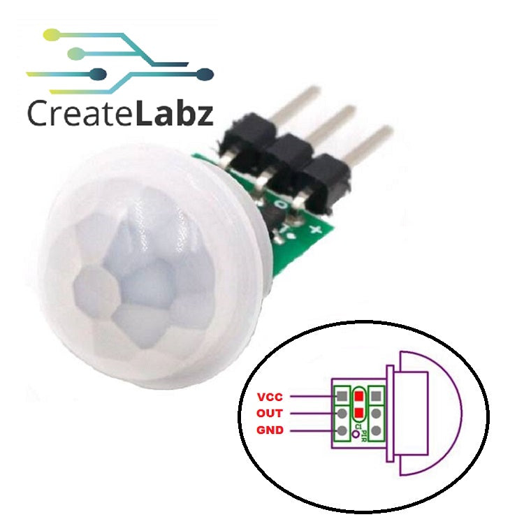
The mini PIR (Passive Infrared) sensor is a small motion-detecting module that senses infrared radiation emitted by warm objects like humans or animals. It's commonly used in security systems, smart devices, and automation projects to detect movement within a certain range. Compact and energy-efficient, the mini PIR sensor is easy to use with microcontrollers like Arduino or ESP32 for triggering actions such as turning on lights, capturing photos, or activating alarms.
Specifications:
- Detection range: 3–6 meters (varies by model)
- Detection angle: ~110°
- Operating voltage: 3.3V to 5V
- Output: Digital HIGH/LOW signal
- Warm-up time: ~10–60 seconds after powering on
- Dimensions: ~24mm × 32mm × 18mm (typical mini sensor)

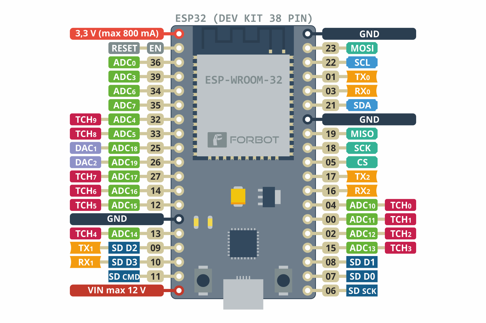
The ESP32 is a versatile microcontroller with built-in Wi-Fi and Bluetooth, ideal for IoT, home automation, robotics, and wearable projects. It features a dual-core processor, multiple input/output pins, and supports various interfaces.
Specifications:
- CPU: Dual-core Xtensa® 32-bit LX6 @ up to 240 MHz
- RAM: 520 KB SRAM
- Flash: Typically 4 MB (varies by board)
- Operating voltage: 3.3 V
- Wi-Fi: 802.11 b/g/n
- Bluetooth: v4.2 BR/EDR and BLE
- GPIO pins: Up to 34 (depending on module)
- Common modules: ESP32-WROOM-32, ESP32-WROVER, ESP32-C3
Pinout:
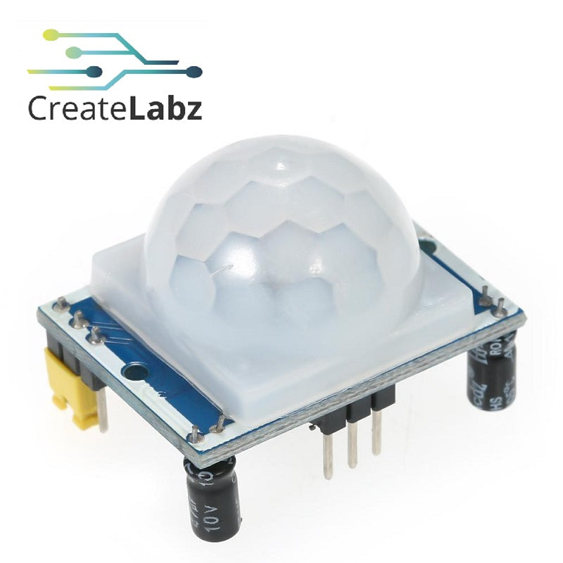
A PIR (Passive Infrared) sensor detects motion by sensing the infrared radiation emitted by warm objects like humans and animals. It is widely used in security systems, lighting automation, and IoT projects to trigger actions such as alarms, lights, or camera captures when motion is detected.
Specifications:
- Detection range: 3 to 7 meters (typical)
- Detection angle: ~100° to 120°
- Operating voltage: 3.3V to 5V
- Output: Digital HIGH (motion), LOW (no motion)
- Warm-up time: ~30 to 60 seconds after power-on
- Common models: HC-SR501, AM312 (mini), SR602

OLED (Organic Light-Emitting Diode) is a self-light-emitting technology composed of a thin, multi-layered organic film placed between an anode and cathode. In contrast to LCD technology, OLED does not require a backlight.
Specifications:
- Display Type: OLED (monochrome)
- Resolution: 128 x 64 pixels
- Interface: I2C (often SDA/SCL) or SPI (variant-dependent)
- Viewing Angle: Nearly 180°
- Operating Voltage: 3.3V – 5V
- Power Consumption: ~0.06–0.08W
- Driver IC: SSD1306 (most common)
- Screen Size: Typically 0.96" or 1.3" diagonal
-
Color Options: Usually white, blue, or yellow
Hardware Setup
Version 1:
Version 2:
Wiring Set-up
Version 1:
|
ESP32-CAM Pin |
Connected To |
|
GPIO 16 |
PIR Sensor OUT |
|
GPIO 13 (PWM) |
Servo Motor Signal Pin |
|
GPIO 15 (SDA) |
LCD I2C SDA |
|
GPIO 14 (SCL) |
LCD I2C SCL |
|
3.3V |
PIR Sensor VCC |
|
5V (External) |
Servo Motor VCC (use external 5V supply) |
|
GND |
PIR Sensor GND, LCD GND, Servo GND |
Version 2:
ESP32
|
ESP32 Pin |
Connected To |
|
GPIO 25 (PWM) |
Servo Motor Signal Pin |
|
GPIO 21 (SDA) |
OLED Display SDA |
|
GPIO 22 (SCL) |
OLED Display SCL |
|
3.3V |
OLED Display VCC |
|
GND |
OLED Display GND, Servo Motor GND |
|
5V (External) |
Servo Motor VCC (use external power) |
ESP32-CAM
|
ESP32-CAM Pin |
Connected To |
|
GPIO 13 |
PIR Sensor OUT (Motion Detection) |
|
GPIO 32 |
Camera Power Down (PWDN) |
|
GPIO 0 |
Camera Clock (XCLK) |
|
GPIO 26 |
Camera SIOD (I2C Data) |
|
GPIO 27 |
Camera SIOC (I2C Clock) |
|
GPIO 35 |
Camera D7 (Y9) |
|
GPIO 34 |
Camera D6 (Y8) |
|
GPIO 39 |
Camera D5 (Y7) |
|
GPIO 36 |
Camera D4 (Y6) |
|
GPIO 21 |
Camera D3 (Y5) |
|
GPIO 19 |
Camera D2 (Y4) |
|
GPIO 18 |
Camera D1 (Y3) |
|
GPIO 5 |
Camera D0 (Y2) |
|
GPIO 25 |
Camera VSYNC |
|
GPIO 23 |
Camera HREF |
|
GPIO 22 |
Camera PCLK |
|
3.3V |
PIR Sensor VCC |
|
GND |
PIR Sensor GND, Camera GND |
|
MicroSD Card Slot |
SD Card Storage |
Software Setup
Version 1: with LCD Countdown using ESP32-CAM
ESP32-CAM Code
    // === PIN ASSIGNMENTS ===
    #define PIR_PIN     16    // PIR Sensor
    #define SERVO_PIN   13    // Servo Motor
    #define SDA_PIN     15    // LCD SDA
    #define SCL_PIN     14    // LCD SCL

    LiquidCrystal_I2C lcd(0x27, 16, 2);
    Servo feederServo;
    bool hasFed = false;
    unsigned long lastFeedTime = 0;
    const unsigned long cooldownPeriod = 10000; // 10 seconds cooldown

    void setup() {
      Serial.begin(115200);

      // LCD Initialization
      Wire.begin(SDA_PIN, SCL_PIN);
      lcd.begin(16, 2);
      lcd.backlight();
      lcd.setCursor(0, 0);
      lcd.print("Pet Feeder Ready");
      lcd.setCursor(0, 1);
      lcd.print("Warming PIR...");

      // PIR sensor setup with internal pull-down
      pinMode(PIR_PIN, INPUT_PULLDOWN);
      delay(10000);  // Warm-up delay for PIR sensor
      Serial.println("✅ PIR Warmed up.");

      // Servo initialization
      feederServo.setPeriodHertz(50);
      feederServo.attach(SERVO_PIN);
      feederServo.write(0);  // Closed

      lcd.clear();
      lcd.setCursor(0, 0);
      lcd.print("Waiting for pet...");
    }

    void loop() {
      // Debounce: read PIR twice to confirm motion
      int motion = digitalRead(PIR_PIN);
      delay(50);
      int confirm = digitalRead(PIR_PIN);
      unsigned long currentTime = millis();

      if (motion == HIGH && confirm == HIGH && !hasFed) {
        hasFed = true;
        lastFeedTime = currentTime;

        Serial.println("🎯 Motion Confirmed!");
        lcd.clear();
        lcd.setCursor(0, 0);
        lcd.print("Pet Detected");
        lcd.setCursor(0, 1);
        lcd.print("Dispensing...");

        // Dispense food via servo
        feederServo.write(90);
        delay(1500);
        feederServo.write(0);
        delay(500);

        lcd.clear();
        lcd.setCursor(0, 0);
        lcd.print("Feeding Done!");
        delay(3000);

        lcd.clear();
        lcd.setCursor(0, 0);
        lcd.print("Waiting...");
      }

      // Reset feeding flag after cooldown
      if (hasFed && (currentTime - lastFeedTime > cooldownPeriod)) {
        hasFed = false;
        Serial.println("⏳ Cooldown complete. Ready for next detection.");
      }

      delay(200);
    }
Version 2: with OLED Countdown using ESP32-CAM and ESP32
ESP32-CAM Code
    #include "esp_camera.h"
    #include "FS.h"
    #include "SD_MMC.h"


    #define PIR_PIN 13  // GPIO connected to PIR OUT


    // CAMERA MODEL - AI Thinker
    #define PWDN_GPIO_NUM     32
    #define RESET_GPIO_NUM    -1
    #define XCLK_GPIO_NUM      0
    #define SIOD_GPIO_NUM     26
    #define SIOC_GPIO_NUM     27


    #define Y9_GPIO_NUM       35
    #define Y8_GPIO_NUM       34
    #define Y7_GPIO_NUM       39
    #define Y6_GPIO_NUM       36
    #define Y5_GPIO_NUM       21
    #define Y4_GPIO_NUM       19
    #define Y3_GPIO_NUM       18
    #define Y2_GPIO_NUM        5
    #define VSYNC_GPIO_NUM    25
    #define HREF_GPIO_NUM     23
    #define PCLK_GPIO_NUM     22


    int photoIndex = 0;
    bool motionPreviouslyDetected = false;
    unsigned long lastCaptureTime = 0;
    const unsigned long captureCooldown = 10000; // 10 sec cooldown between photos


    void startCamera() {
      camera_config_t config;
      config.ledc_channel = LEDC_CHANNEL_0;
      config.ledc_timer   = LEDC_TIMER_0;
      config.pin_d0       = Y2_GPIO_NUM;
      config.pin_d1       = Y3_GPIO_NUM;
      config.pin_d2       = Y4_GPIO_NUM;
      config.pin_d3       = Y5_GPIO_NUM;
      config.pin_d4       = Y6_GPIO_NUM;
      config.pin_d5       = Y7_GPIO_NUM;
      config.pin_d6       = Y8_GPIO_NUM;
      config.pin_d7       = Y9_GPIO_NUM;
      config.pin_xclk     = XCLK_GPIO_NUM;
      config.pin_pclk     = PCLK_GPIO_NUM;
      config.pin_vsync    = VSYNC_GPIO_NUM;
      config.pin_href     = HREF_GPIO_NUM;
      config.pin_sscb_sda = SIOD_GPIO_NUM;
      config.pin_sscb_scl = SIOC_GPIO_NUM;
      config.pin_pwdn     = PWDN_GPIO_NUM;
      config.pin_reset    = RESET_GPIO_NUM;
      config.xclk_freq_hz = 20000000;
      config.pixel_format = PIXFORMAT_JPEG;

      config.frame_size   = FRAMESIZE_SVGA; // try FRAMESIZE_VGA if needed
      config.jpeg_quality = 10;
      config.fb_count     = 1;


      esp_err_t err = esp_camera_init(&config);
       if (err != ESP_OK) {
          Serial.printf("Camera init failed with error 0x%x", err);
          while (true);
      }
  }

    void setup() {
      Serial.begin(115200);
      delay(1000);

      pinMode(PIR_PIN, INPUT);

      startCamera();

    if (!SD_MMC.begin()) {
      Serial.println("SD Card Mount Failed");
      return;
    }


    if (SD_MMC.cardType() == CARD_NONE) {
      Serial.println("No SD card attached");
      return;
    }


    Serial.println("System ready. Waiting for motion...");
  }


void loop() {
  bool motionDetected = digitalRead(PIR_PIN) == HIGH;


  if (motionDetected && !motionPreviouslyDetected && millis() - lastCaptureTime > captureCooldown) {
    Serial.write('A');


    camera_fb_t * fb = esp_camera_fb_get();
    if (!fb) {
      Serial.println("Camera capture failed");
      return;
    }


    String path = "/photo" + String(photoIndex++) + ".jpg";
    File file = SD_MMC.open(path, FILE_WRITE);
    if (!file) {
      Serial.println("Failed to open file");
      esp_camera_fb_return(fb);
      return;
    }


    file.write(fb->buf, fb->len);
    file.close();
    esp_camera_fb_return(fb);


    Serial.println("Photo saved to: " + path);


    lastCaptureTime = millis(); // start cooldown
  }


  motionPreviouslyDetected = motionDetected;
  delay(10000); // 10 secs delay
  }
ESP32 Code
    // === OLED Setup ===
    #define SCREEN_WIDTH 128
    #define SCREEN_HEIGHT 64
    #define OLED_ADDRESS 0x3C


    Adafruit_SSD1306 display(SCREEN_WIDTH, SCREEN_HEIGHT, &Wire, -1);


    // === Servo Setup ===
    #define SERVO_PIN 25
    Servo myServo;


    void setup() {
      Serial.begin(115200);


      // Initialize OLED
      if (!display.begin(SSD1306_SWITCHCAPVCC, OLED_ADDRESS)) {
        Serial.println(F("OLED not found"));
        while (1);
      }


      display.clearDisplay();
      display.setTextSize(1);
      display.setTextColor(SSD1306_WHITE);
      display.setCursor(30, 25);
      display.println("OLED Ready");
      display.display();
      delay(1000);


      // Initialize Servo
      myServo.setPeriodHertz(50);
      myServo.attach(SERVO_PIN);
      myServo.write(0);
      Serial.println("Servo Ready");
      delay(1000);
    }

    void open(){
    for (int i = 3; i > 0; i--) {
        display.clearDisplay();
        display.setTextSize(1);
        display.setCursor(25, 15);
        display.println("DISPENSING IN...");
        display.setTextSize(2);
        display.setCursor(60, 35);
        display.print(i);
        display.display();
        delay(1000);
      }


      // Dispense (Open Servo)
      myServo.write(90);
      display.clearDisplay();
      display.setTextSize(1);
      display.setCursor(34, 28);
      display.println("DISPENSING...");
      display.display();
      Serial.println("Dispensing...");
      delay(1000);


      // Countdown to Close
      for (int i = 3; i > 0; i--) {
        display.clearDisplay();
        display.setTextSize(1);
        display.setCursor(30, 15);
        display.println("CLOSING IN...");
        display.setTextSize(2);
        display.setCursor(60, 35);
        display.print(i);
        display.display();
        delay(1000);
      }


      // Close Servo
      myServo.write(0);
      display.clearDisplay();
      display.setTextSize(1);
      display.setCursor(44, 28);
      display.println("DONE!");
      display.display();
      Serial.println("Dispense Complete");
      }

      void loop() {
      byte recv=0;
      if (Serial.available()){
        recv = Serial.read();
        if (recv == 'A'){
        open();
        }
      }
    }
Code Breakdown
Version 1:
Libraries Used
Wire.h
- Enables I2C communication for devices like the LCD.
LiquidCrystal_I2C.h
- Controls a 16x2 I2C LCD display for showing status messages.
ESP32Servo.h
- Allows the ESP32 to generate PWM signals to control a servo motor.
Constants & Macros
#define PIR_PIN 16 // PIR Sensor
#define SERVO_PIN 13 // Servo Motor
#define SDA_PIN 15 // LCD SDA
#define SCL_PIN 14 // LCD SCL
- PIR_PIN: GPIO pin for the PIR sensor (detects motion).
- SERVO_PIN: GPIO pin controlling the servo motor for food dispensing.
- DA_PIN / SCL_PIN: I2C pins for communication with the LCD screen.
Global Objects & Variables
- lcd: Creates an LCD object at I2C address 0x27 for a 16x2 character display.
- feederServo: Creates a servo motor object.
- hasFed: Tracks if the pet has been fed already to avoid double dispensing.
- lastFeedTime: Stores the timestamp of the last feeding.
- cooldownPeriod: Prevents feeding again within 10 seconds.
setup() Function
-
Initializes the LCD display, PIR sensor, and servo motor to prepare the system for detecting motion and dispensing food.
- Start Serial Communication - Used for debugging messages.
- Initialize LCD Display - Configures SDA/SCL pins for I2C communication. Turns on LCD backlight and displays “Pet Feeder Ready”.
- PIR Sensor Warm-Up - Configures PIR sensor pin with internal pull-down resistor. Waits 10 seconds for the sensor to stabilize.
- Initialize Servo Motor - Sets PWM frequency. Moves servo to closed position (0°) to ensure no food is dispensed at startup.
loop() Function
-
Continuously checks for motion. When motion is detected, it dispenses food and enforces a cooldown before allowing another feeding.
- Debounce PIR Sensor - Reads the PIR sensor twice with a short delay to confirm motion.
-
Trigger Feeding Sequence - If motion is confirmed and the system hasn’t fed recently:
- Activates servo to dispense food.
- Displays “Pet Detected” and “Dispensing...” on LCD.
- Cooldown Logic - Prevents multiple feedings within the 10-second cooldown period.
- Idle Display - Shows “Waiting...” on LCD while monitoring for motion.
Version 2:
ESP32-CAM Code Breakdown
Libraries Used
esp_camera.h
- Provides functions for initializing and capturing images from the ESP32-CAM. Handles camera configuration and JPEG encoding.
FS.h
- Abstracts file system operations for devices like SD cards. Used for reading/writing files.
SD_MMC.h
- Enables communication with microSD cards over the SD/MMC interface. Provides methods to mount the SD card, open files, and write captured images.
Constants & Macros
PIR_PIN
- GPIO pin connected to the PIR motion sensor output.
Camera Pin Definitions
- Assign ESP32 pins for data, clock, and control signals of the AI Thinker ESP32-CAM module. Each constant maps a specific hardware function to its respective GPIO.
Global Variables
- photoIndex: Used to incrementally name saved photos (photo0.jpg, photo1.jpg, etc.).
- motionPreviouslyDetected: Tracks motion state to avoid multiple captures for one motion event.
- lastCaptureTime: Stores the timestamp of the last photo to enforce a cooldown.
- captureCooldown: Sets a 10-second wait between photo captures.
startCamera() Function
-
Configures and initializes the ESP32-CAM hardware.
- Assigns all camera pins (data, clock, sync, control) to their GPIOs.
- Sets camera resolution, pixel format (JPEG), and JPEG quality.
- Calls esp_camera_init() to initialize the camera driver.
- Stops the program if initialization fails.
setup() Function
-
Initializes peripherals (serial, PIR sensor, camera, SD card) and prepares the system for operation.
- Starts serial communication for debugging.
- Configures PIR sensor pin.
- Calls startCamera() to prepare the ESP32-CAM.
- Mounts the SD card and checks if it’s connected.
- Prints “System ready” once all components are set.
loop() Function
-
Continuously checks for motion events and saves photos to SD card if motion is detected.
- Motion Detection: Reads PIR sensor state to detect movement.
- Cooldown Check: Ensures at least 10 seconds have passed since the last photo.
- Capture & Save Image: If motion is detected, triggers camera to capture a frame. Saves the image as photoX.jpg on the SD card. Prints file path to Serial.
- Serial.read(): Reads one byte (character) of data from the serial buffer.
- Motion State Update: Tracks whether motion is ongoing to avoid repeated triggers.
- Delay: Waits briefly to prevent excessive CPU use in the loop.
Saving Images
- Captures a frame buffer from the camera.
- Writes JPEG data directly to the SD card.
- Frees up the frame buffer after use to save memory.
ESP32 Code Breakdown
Libraries Used
Wire.h
- Enables I2C communication between the ESP32 and the OLED display.
Adafruit_GFX.h
- Provides graphics functions like drawing text, shapes, and images on the display.
Adafruit_SSD1306.h
- A driver library to control SSD1306 OLED displays over I2C.
ESP32Servo.h
- Allows the ESP32 to generate PWM signals to control a servo motor.
Constants & Macros
#define SCREEN_WIDTH 128
#define SCREEN_HEIGHT 64
#define OLED_ADDRESS 0x3C
#define SERVO_PIN 25
- SCREEN_WIDTH & SCREEN_HEIGHT: Define the OLED display size as 128x64 pixels.
- OLED_ADDRESS: Sets the OLED’s I2C address (0x3C for most SSD1306 modules).
- SERVO_PIN: Assigns GPIO pin 25 for controlling the servo motor.
- Global Objects
- display: Object to control the OLED display.
- myServo: Object to control the servo motor.
setup() Function
-
Initializes all hardware components (serial, OLED display, and servo motor) and prepares the system for operation.
- Start Serial Communication: Begins communication at 115200 baud for debugging and control.
- Initialize OLED Display: Checks if the OLED screen is connected and functional. If not found, stops the program. Shows “OLED Ready” for 1 second if successful.
- Initialize Servo Motor: Sets PWM frequency to 50Hz (standard for hobby servos). Connects the servo to the specified pin and moves it to its closed position (0°). Prints “Servo Ready” to confirm setup.
void open() Function
-
Controls the dispensing sequence, including countdowns on the OLED display and moving the servo motor to simulate dispensing.
- Pre-Dispense Countdown: Displays “DISPENSING IN...” with a countdown (3…2…1) on the OLED before starting.
- Activate Servo: Rotates the servo to 90° (open position) to dispense. Shows “DISPENSING...” on the OLED and logs to Serial Monitor.
- Post-Dispense Countdown: Displays “CLOSING IN...” with a countdown (3…2…1) before closing.
- Deactivate Servo: Rotates the servo back to 0° (closed position). Shows “DONE!” on OLED and logs “Dispense Complete”.
void loop() Function
-
Continuously checks for serial input and triggers the dispensing sequence when the ‘A’ command is received.
- Serial Check: Looks for incoming data from the Serial Monitor.
- Serial.write(): Reads the received character. If it matches ‘A’, it calls the open() function to start dispensing.
- Repeat Forever: Keeps running in a loop, waiting for the next command.
Video Demonstration
Version 1:
Version 2:
Conclusion
This project addresses a common challenge faced by many pet owners—ensuring their pets are fed on time despite busy schedules. By integrating motion detection, automated feeding, visual countdown, and image capture, the smart pet feeder offers a reliable and efficient solution for modern pet care.
Two versions of the project were made to accommodate varying user preferences. The first version utilizes a 16x2 LCD display and a single ESP32-CAM module to detect motion and activate the servo motor for food dispensing. The second, more advanced version employs an OLED display and a dual-microcontroller setup—an ESP32-CAM for motion detection and photo capture, and a separate ESP32 for display control and servo operation. This configuration not only improves performance but also enhances user experience by providing real-time visual feedback and image documentation.
Through the use of accessible hardware components such as the ESP32-CAM, MG996R servo motor, PIR sensor, and display modules, this project demonstrates how embedded systems can be effectively applied to solve everyday problems. Ultimately, the smart pet feeder serves as a practical and scalable solution for improving pet care through automation and IoT technology.
Project Authors (Code Delta)
- Janine Ernie G. Cabuslay
- James Robert L. Machico
- Cheryl Lou B. Narvaez
References
- Github: PierceBrandies - PetFeeder
- Hackster.io - craftiarenko automatic pet feeder
- Youtube


