Overview
An Intruder Detection System is an IoT-based security solution that leverages the capabilities of the ESP32 microcontroller and the Blynk app platform. The ESP32, known for its Wi-Fi and Bluetooth capabilities, acts as the core of the system, interfacing with various sensors, such as PIR motion sensors and light sensors, to detect unauthorized access or suspicious activity. The Blynk Cloud platform provides a user-friendly interface for monitoring and controlling the system remotely. By integrating the ESP32 with Blynk, users can receive real-time alerts, notifications, and status updates directly on their smartphones, regardless of their location.
In this tutorial, we will be using ESP32 and Blynk Cloud to make an intruder detection system. This project is perfect for enhancing our home and office security.
Hardware Used
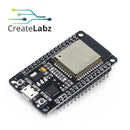
- DoIT ESP32 30pins
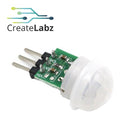
- Mini PIR Motion Sensor AM312, 2.7V-12V
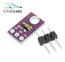
- TEMT6000 Ambient Light Sensor Module
- Breadboard
- Jumper Wires
- Resistor
- Red LED (Indication purposes only)
Software Used
Application Discussion
- DoIT ESP32 30pins, Development Board WiFi+Bluetooth Ultra Low Power

The ESP-32 DEVKIT DOIT is a development board that is built around the powerful ESP32 system on a chip microcontroller. It is a development platform with a programmer, Serial-to-USB module, voltage regulator, and several peripherals. The most relevant: it combines WiFi and Bluetooth wireless capabilities and it’s dual-core for more complex tasks that demand to multitask.
Specifications:
- It has Wi-Fi and Bluetooth built-in.
- It runs 32-bit programs.
- The clock frequency can go up to 240MHz and it has a 512 kB RAM.
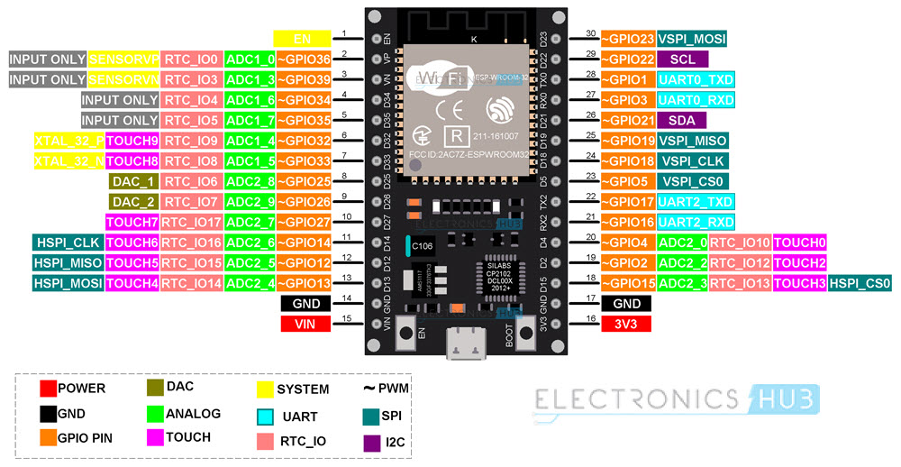
- This particular board has 30 pins, 15 in each row.
- It also has a wide variety of peripherals available, like capacitive touch, ADCs, DACs, UART, SPI, I2C, and much more.
- It comes with a built-in hall effect sensor and a built-in temperature sensor.
ESP32 PINOUT

- Mini PIR Motion Sensor AM312, 2.7V-12V

This motion sensor is a mini version of the standard PIR sensor. This type of sensor can be used to detect movement by means of infrared light. PIR sensors are used to sense the movement of people, animals, or other objects. They are commonly used in burglar alarms and automatically activated lighting systems. They are commonly called simply "PIR", or sometimes "PID", for "passive infrared detector". These sensors can be used with microcontroller boards like Arduino.
Features:
- Low power consumption, small size, easy to install.
- Internal use of digital signal processing, pit interference strong.
- High sensitivity, reliability, and can be widely used in the automatic sensing circuit.
- Repeatable trigger mode: that is, after the induction output is high, in the delay period, if the body in its induction range of activities, the output will remain high until the delay after the person becomes Low level. (Ie, the sensing module automatically detects a delay period after each activity of the human body, and takes the last active time as the starting point for the delay time).
Technical Parameters:
- Input Voltage: DC 2.7-12V
- Quiescent current: <100uA
- Level output: High 3.3 V/Low 0V
- Delay time: approximately 2 seconds (± 30% deviation)
- Standard detection at approximately 3 meters distance
- PCB dimensions: 10mm*8mm
- Total size: 12mm*27mm
- The angle of Sensor: <100 °
- Working temperature: -20°C - +60°C
- Lens type: Small
Pins:
- Vin (indicated with "+" and/or "U1")
- Out (middle pin)
- GND/ground/min (indicated with "-" and/or "C1")
- TEMT6000 Ambient Light Sensor Module

TEMT6000 is a silicon NPN epitaxial planar photo-transistor in a miniature transparent mold for surface mounting onto a printed circuit board. The device is sensitive to the visible spectrum.
Hardware Setup
Wiring Diagram

- Prepare the components needed.

- Perform wiring connections in the breadboard.

PIR Sensor Pin to ESP32
- Out connected to pin 4
- Gnd connected to gnd pin
- Vin connected to 3v3 pin
Ambient Light Sensor Pin to ESP32
- Out connected to pin 34
- Gnd connected to gnd pin
- VCC connected to 3v3
LED Pin to ESP32 (Indication purposes only)
- Gnd to gnd pin
- Positive to pin 18 (w/ 220 ohms 1/4 watt resistor)
Software Setup
Blynk Cloud Setup
-
Go to Blynk.cloud and log in with your account, or create a new account if you don’t have one.

- Once you log in, go to Templates and Create New Template.
- Name the template as required.
- Select the hardware as Esp32, then click done.

- Go to Datastreams and create Datastreams on the virtual pin as shown.


- Now go to the Events section. Set the event notifications. By doing so, we will enable Blynk to send us instant notifications on our mobile app whenever the system detects any intruder activity.


- In setting up the web dashboard, simply drag an LED, a label, and a switch onto the dashboard and configure them according to the provided settings.
- Don’t forget to click on the save button to preserve your settings.

- Add a new device from the template. Choose the template, give your device a name, and create.


- Copy the provided lines of code. We will need that later.

Arduino IDE Code Setup
- Launch Arduino IDE application.

- In setting up the code, we will first install the required libraries.
-
BlynkSimpleEsp32.h - This library facilitates communication between the ESP32 microcontroller and the Blynk Cloud service. It allows the ESP32 to connect to Blynk’s server and interact with the Blynk mobile app.
- WiFi.h - This library provides functionality for connecting the ESP32 to Wi-Fi networks. It is essential for enabling the ESP32 to communicate with the Blynk Cloud over the internet.
- WiFiClient.h - Part of the core Wi-Fi library for the ESP32, '
WiFiClient'is used to create client connections for communication over TCP/IP, though it's typically used indirectly through higher-level libraries like 'BlynkSimpleEsp32.h.' - TimeLib.h - This library provides time-related functions for managing and formatting time on the ESP32. It is used to handle and manipulate time values.
- ESP32Time.h - This library extends the capabilities of time management on the ESP32 by providing additional functions for time manipulation and handling.

- Replace these three lines of code with the ones you copied earlier.
- This is from Blynk.cloud after you created a new device.

- Then change your SSID and password according to your wifi credentials.

- In the code, we are continuously reading the human presence sensor and saving the value in a variable.
- Either the PIR sensor or the light sensor can trigger the alarm.
- We are updating the Blynk virtual pins every 1 second.
- If an intruder is detected, a warning message is sent to the dashboard, and the LED turns on.
- A notification is sent every minute.

- Now let's select the correct board and compile the code to make sure that everything is correct.
- Now let's upload the code to our esp32. Select the correct board and port, then click upload.


Blynk App Setup
- Log in to your account and open the template we already set up on the web.

- Click the wrench button and add widgets. The same as what you’ve set up on the web earlier.

- Feel free to customize the design and colors of the widgets according to your specific preferences.

- After everything is set up go back to open the mobile dashboard.

Video Demonstration
Conclusion
The Intruder Detection System using ESP32 and Blynk effectively demonstrates how modern microcontroller technology and IoT platforms can be harnessed to enhance security. The system reliably detects motion using a PIR sensor and monitors ambient light levels to distinguish between day and night conditions. Notifications and alarms are managed through the Blynk app, allowing for real-time updates and remote control. The system’s integration with Blynk ensures seamless communication, while the ESP32 provides the necessary computational and connectivity capabilities. The PIR sensor successfully detects movement and triggers the alarm and notifications as intended. The light sensor provides additional context for detecting intruders, especially in low-light conditions. The Blynk app effectively sends notifications and allows for remote management of the system, enhancing user control and responsiveness.
Suggested related projects and improvements include camera integration by adding a camera module to capture images or video when motion is detected. This provides visual verification of intrusions and can be integrated with Blynk for remote viewing. Also, by adding door and window sensors, integrate contact sensors on doors and windows to expand the detection capabilities beyond motion sensing. Provide more comprehensive coverage by detecting unauthorized entry at specific points of access.
References
- https://arduinoyard.com/arduino-intruder-alarm-system-esp32-blynk/
- https://docs.sunfounder.com/projects/umsk/en/latest/03_esp32/esp32_lesson49_blynk.html


