Overview
This project involves creating a simple heartbeat monitoring system using the Seeeduino Xiao microcontroller. It integrates a heartbeat sensor to measure pulse, an RGB LED for visual feedback, and an OLED display to show real-time heart rate. The RGB LED changes color based on the heart rate, while the OLED displays the actual beats per minute (BPM).
Hardware Used
Software Used
Application Discussion
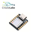
- Seeed Studio XIAO SAMD21 Cortex M0+(Seeeduino XIAO)-Arduino module

The Seeeduino XIAO is a compact, Arduino-compatible microcontroller development board produced by Seeed Studio. Designed for projects that require a small form factor and low power consumption, it is ideal for applications like wearable devices, small robots, and Internet of Things (IoT) projects.
Specifications:
- CPU: ARM Cortex-M0+ CPU(SAMD21G18) running at up to 48MHz
- Storage: 256KB Flash,32KB SRAM
- I/O PINs: 14 GPIO PINs,11 analog PINs, 11 digital PINs, 1 DAC output Pin
- Interface: 1 I2C interface,1 UART interface, 1 SPI interface, USB Type-C interface
- LEDs: 1 user LED, 1 power LED, and two LEDs for serial port downloading
- Reset button: two reset buttons short connect to reset
- Software compatibility: Arduino IDE
- Dimensions: 21x17.5 mm
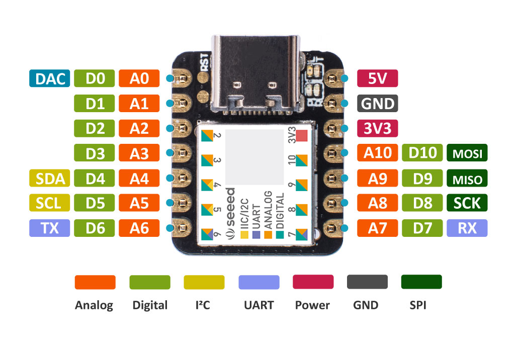
Seeeduino Xiao Pinout

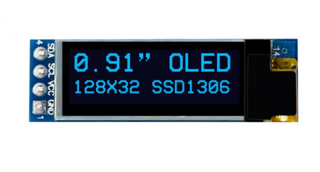
- OLED display module128x32

An OLED (Organic Light Emitting Diode) display module is a type of flat panel display technology that consists of organic compounds that emit light when an electric current is applied. Unlike traditional displays, OLEDs do not require a backlight, as each pixel generates its own light. This results in sharper images, deeper blacks, and higher energy efficiency, especially for displaying darker content.
- Color:Blue
- Model Number:0.91 inch OLED module
- Display Mode:OLED module
- Resolution:128*64
- Type:OLED module
- RGB LED, Diffused

Specifications:
- 5mm / 10mm diameter
- Tricolor Red(R) Green(G) Blue(B) Common Cathode(CC), R:620nm-625nm / G:515nm-523nm / B:450nm-467nm, Luminous Intensity(Brightness): R:1000-2000mcd / G:4000-5000mcd / B:3000-4000mcd, Viewing Angle: 20-50 Degrees
- Parameters : DC 1.8V-2.2V(R) 3V-3.4V (G/B) Volt 20mA, Polarity (2 V) : Cathode "-" (Longer Leg) | Anode "+" (Shorter Leg), Foggy Round Small Lens
- Led diode(Through Hole DIP 4pins leads mini LEDs Set) Three Colour
- Compatible with: DIY PCB Board Circuit, Arduino, Raspberry Pi, Hobby, Science Experiments, Throwies Project, Breadboard, Bulb, Bulk Parts Replacement
- 4 pin, Tiny Bright Light, Low Voltage & Low Power Consumption, 1.8v 2.2v 3.2v 3.4v
RGB LED PINOUT

- Heart Rate Pulse Sensor

A heart rate pulse sensor is an electronic sensor that measures a person's heart rate, typically by detecting the pulse from blood flow through the skin. It’s commonly used in fitness trackers, wearable devices, and biomedical applications to monitor cardiovascular activity in real-time.
Specification:
- Working voltage: 5V
- Working current: 4mA
- Diameter: 16MM
- Magnification: 330
- LED wavelength: 609 nm
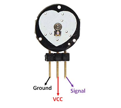
HEART RATE PULSE SENSOR PINOUT

Hardware Setup
Wiring Diagram

- Prepare the components needed.
- Perform wiring connections in the breadboard.

-
Connect the Heartbeat Sensor:
- The heartbeat sensor typically has three pins: VCC (power), GND (ground), and Signal (data).
- Connect VCC to the 5V pin on the Seeeduino Xiao, GND to the ground, and Signal to an analog input pin (e.g., A0).
-
Connect the RGB LED:
- RGB LEDs usually have four pins: R (Red), G (Green), B (Blue), and Common Ground (GND)
- Connect the common ground pin to GND on the Seeeduino, and the R, G, and B pins to different digital pins on the Seeeduino (e.g., D1, D2, and D3).
-
Connect the OLED Display:
- If you’re using an I2C OLED display, it will have four pins: VCC, GND, SCL (clock), and SDA (data).
- Connect VCC to 3.3V, GND to ground, and SCL and SDA to the corresponding I2C pins on the Seeeduino (SCL to D4, SDA to D5).
-
Write the Code:
- You’ll need to write a program that:
- Reads analog data from the heartbeat sensor.
- Processes the data to calculate beats per minute (BPM).
- Controls the RGB LED based on the BPM (e.g., green for normal, red for high).
- Sends the calculated BPM to the OLED display for real-time monitoring.
- You’ll need to write a program that:
Software Setup
Code Breakdown:
-
readHeartbeat(): This function will read and process data from the heartbeat sensor and return the BPM. -
displayHeartbeat(bpm): Sends the BPM to the OLED for display. -
setRGBColor(bpm): Changes the RGB LED color depending on the heart rate.
Testing and Calibration:
- Test your sensor by placing it on your finger or wrist.
- Adjust your code as needed to ensure the readings and visual feedback are accurate.
Final Adjustments:
- Once everything works, you can solder your components onto a protoboard for a more permanent setup.
- Optionally, add a case or enclosure to make the project portable and durable.
This should guide you through building and coding your heartbeat sensor project!
Video Demonstration
In conclusion, this heartbeat sensor project using the Seeeduino Xiao, RGB LED, and OLED display offers a practical and hands-on way to learn key skills in microcontroller programming, sensor data processing, and hardware interfacing. It provides valuable insights into real-time health monitoring systems, blending both hardware and software to create an efficient and user-friendly solution. Through this project, you’ll develop problem-solving abilities and a deeper understanding of embedded systems, making it a great stepping stone into IoT and wearable technology applications.
References
- Seeeduino Xiao Overview and Tutorials
- Pulse Sensor Guide
- Using OLED Displays with Arduino
- RGB LED Arduino Guide


