

Overview
Have you ever wondered how to control your home devices even if you aren’t at home? Worry no more, this project will help regulate the room’s temperature and humidity and control home devices with just a simple click of a button from your smartphone.
This project aims to build a system that can detect the temperature and humidity of a certain room, post those values in an online server, and at the same time, control a specific home device (like a Fan or a lamp) through manual clicking of a button or digital clicking of a button using your smartphone.
Hardware Components
IOT (Internet Of Things) KIT 1 Wemos D1 mini Pro + 32MB Flash + Shields
Components used in the kit:
Software Components
- Arduino IDE
- Blynk app (Google Play Store, iTunes App Store)
Application Discussion
Wemos D1 Mini Pro
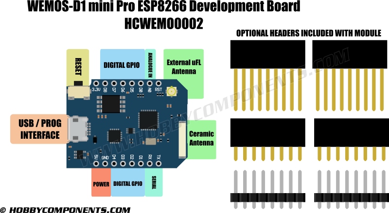
The WeMos D1 min PRO is a miniature wireless 802.11 (Wifi) microcontroller development board. This microcontroller board already has the ESP8266 microcontroller in it. You still use your Arduino IDE to program and control this board.
You can also stack WeMos shields that have other functionalities such as button shield, contact relay shield, and DHT11 humidity and temperature shield, which we will use in this project.
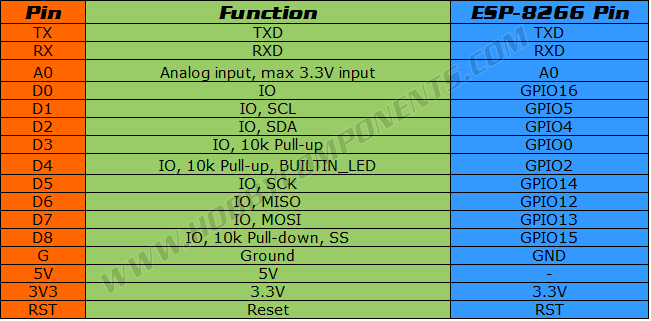
Below are the pin configurations for both the WeMos D1 Mini pro board and ESP8266 and their functions.
Features
-
11 digital input/output pins
-
Interrupt/Pulse Width Modulation(PWM)/I2C/one-wire
-
1 analog input(3.2V max input)
-
16M bytes(128M bit) Flash
-
External antenna connector
-
Built-in ceramic antenna
-
New CP2104 USB-TO-UART IC
-
Same size as D1 mini, but more light
Technical details [1]
| Microcontroller | ESP-8266EX |
|---|---|
| Operating Voltage | 3.3V |
| Digital I/O Pins | 11 |
| Analog Input Pins | 1(Max input: 3.2V) |
| Clock Speed | 80MHz/160MHz |
| Flash | 16M bytes |
| Length | 34.2mm |
| Width | 25.6mm |
| Weight | 2.5g |
DHT11 Sensor Shield
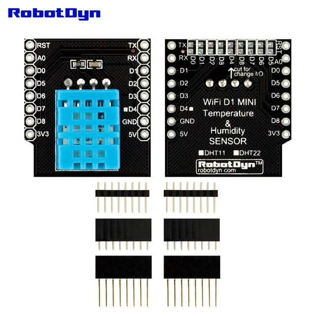
Wemos offers a wide range of expansion or shields that you can just stack on top of any Wemos board. One of this is the DHT11 Humidity and Temperature Sensor shield. This shield receives and sends humidity and temperature data to the Wemos board. It specifically uses D4 of the Wemos D1 Mini Pro board, which is a drawback since you can’t change the pin designation of this sensor shield.
Features
-
Temperature: -20~60°C (±0.5°C)
-
Humidity: 20-95%RH (±5%RH)
Contact Relay Shield

Another shield offer by Wemos is the contact relay shield. Just like a normal relay module, it closes or opens any circuit when the signal pin is triggered. The signal pin of the relay shield is pin D1, which is also unchangeable.
Features
-
Normally Open (NO): 5A(250VAC/30VDC), 10A(125VAC), MAX:1250VA/150W
-
Normally Closed: 3A(250VAC/30VDC), MAX:750VA/90W
-
7 configurable IO (Default: D1)
Button Shield

The last shield that we will be using in this project is the button shield which is the manual control of the relay. This button is a normally open button which means that if you click the button, it closes the circuit system and activates something. It uses pin D3 of the board which is also unchangeable.
This button shield can be connected to pin D3, which has an internal 10 kiloOhm pull-up resistor and pin D8, which has an internal 10 kiloOhm pull-down resistor.
What is Blynk?
Blynk is a mobile platform for iOS and Android apps to control Arduino, Raspberry Pi and other boards over the internet.
It’s a digital dashboard where you can build a graphic interface for your project by simply dragging and dropping widgets.
It’s really simple to set everything up and you’ll start tinkering in less than 5 mins.
Blynk is not tied to some specific board or shield. Instead, it’s supporting hardware of your choice. Whether your Arduino or Raspberry Pi is linked to the Internet over Wi-Fi, Ethernet or this new ESP8266 chip, Blynk will get you online and ready for the Internet Of Your Things. [3]
Set-up the Hardware and Software
Hardware setup
Before you proceed with the hardware connection setup, you have to solder the header pins first to the Wemos D1 Mini Pro board, contact relay shield, button shield, and DHT11 shield. Here are some pics and gifs to guide you.
First, you have to solder the header pins to the Wemos D1 Mini Pro board.

Then, solder the header pins to the button shield and stack it on top of the WeMos D1 Mini Pro board. This should be the output after stacking the two of them.

Then, solder the header pins to the contact relay shield.

Finally, solder the header pins to the DHT11 shield.

Now, you can start setting up the wiring configuration. Just follow the Fritzing diagram.


For the wiring guide in the Fritzing pic, only the button shield can be seen. But in actual hardware setup, the Wemos D1 Mini Pro, Contact Relay Shield, and Button Shield are stacked together respectively.
Blynk setup
Download the Blynk app for your smartphone on your phone’s Google Play Store or iTunes App Store.
After downloading the app, click the app and it will direct you to the Log In page. You may either Log In with your Facebook Account, or Create New Account, or Log In if you’ve used the Blynk app before. I personally recommend not using the Log In with Facebook Account. You have to make your own account so that the email address you use for logging in will be the default email in which the Auth key will be sent by Blynk.

After signing up or logging in to your account, it will lead you to this screen. Click New Project.

In Create New Project, rename your project. Choose WeMos D1 Mini as the device that you’re using. Connection Type: Wifi. It’s up to you to choose the Theme. After that, click the CREATE button.

After clicking the create button, a dialog box will appear saying that the Auth token was sent to your email. The Auth token will allow your WeMos D1 Mini Pro to connect to the Blynk server when you write and upload your Arduino code. Click the OK button.

Now, let’s start adding the widgets. After clicking the OK button, click the plus (+) sign on the upper right corner of the dashboard.

It will then lead you to the widget box. Click the Button widget.

After placing the button widget on the dahsboard, click the button widget and it will direct you to the Button Settings. Rename your button. The output port should be V4 (Virtual Pin 4). Mode should be a switch. Rename the ON/OFF Labels. After doing all of that, press the back key on the upper left corner.

This will redirect you to the dashboard again. Click the plus sign again to put another widget for the temperature and humidity sensors. In the widget box, click Labeled value. Place two Labeled value widgets on your dashboard. One for Temperature Value and one for Humidity Value.

After putting the two labeled values in your dashboard, click the first one. Rename it. Change the color of the widget. The input port of humidity values should be Virtual Pin 5 (V5). For the label, type /pin.##/%. The two number signs indicate that the widget will show up to 2 decimal places of value. The percent sign is for the unit of measurement of humidity. Reading rate should be PUSH since the WeMos D1 Mini Pro will be the one who will push the data to the Blynk server.

After that, click the back button on the upper left corner and click the other Labeled value widget. Rename it. Change the color of the widget. The input port of temperature values should be Virtual Pin 6 (V6). For the label, type /pin.##/°C. The two number signs indicate that the widget will show up to 2 decimal places of value. The degree Celsius sign is for the unit of measurement of temperature. Reading rate should be PUSH since the WeMos D1 Mini Pro will be the one who will push the data to the Blynk server.

After doing all those steps, your dashboard is complete and ready to test. You can arrange it however you want. Just long press any widget and drag it.

Let’s go to the Arduino IDE setup.
Arduino IDE setup
Open your Arduino IDE. Go to PREFERENCES in your Arduino tab.
Paste the link, which is below this, in your Additional Boards Manager URLs as shown in the image below.
http://arduino.esp8266.com/stable/package_esp8266com_index.json

After that, go to Tools —> Board: —> Boards Manager…
Search for ESP8266 in the search bar and install that board. The INSTALLED sign should appear after you’ve installed it.

After that, go back again to TOOLS —> Board: —> WeMos D1 mini Pro

Before you can start with the code, WeMos D1 Mini Pro uses a different driver for it to connect to the USB port of your laptop. You have to download and install that driver here. You have to restart your PC/MAC for it to be installed properly then open Arduino IDE again.

After installing that driver, your Port (for MAC users) should have this /dev/cu.SLAB_USBtoUART port and click that. For Windows users, your normal COM ports are already the USB to UART ports. They don’t change their name like the ones in MAC devices. Change the Upload Speed to 115200 baud rate so that it will upload faster than when using 9600 baud rate.

Now, you’re ready for the Arduino code.
Copy, paste, and upload the Arduino code below in your Arduino IDE.
If you ever encounter a problem like this picture below.

You must
- Check if D3 and D8 are connected to the GND, and/or
- Unplug and plug the USB connector into your USB port and upload the code again.
It will take a few minutes to upload the code to the board. After it’s uploaded, remove the D3 and D8 wires from the GND so you can use the button shield for clicking.

Now you can manually control the relay or digitall control it on your Blynk mobile app. Have fun tinkering!
Code
Libraries included
ESP8266Wifi.h by Ivan Grokhotkov
This library enables network connection (local and Internet) using the ESP8266 built-in WiFi of the board. With this library, you can instantiate servers, clients and send/receive UDP packets through WiFi. The shield or NodeMCU board can connect either to open or encrypted networks (WEP, WPA). The IP address can be assigned statically or through a DHCP.
SimpleTimer.h by Jean-Francois Turcot
This is (yet another) simple library to launch timed actions. It’s based on millis(), thus it has 1 ms resolution.
It uses polling, so no guarantee can be made about the exact time when a callback is fired. For example, if you set up the library so that it calls a function every 2ms, but this function requires 5ms to complete, then you’ll have an invocation every 5ms.
For applications where non-strict timing is enough, not using interrupts avoids potential problems with global variables shared between the interrupt service routine and the main program, and doesn’t consume a hardware timer.
BlynkSimpleEsp8266.h by Blynk
This is one of the many libraries that is included in the Blynk library zip download. This library helps in the connection of the ESP8266 which is in the WeMos D1 Mini Pro board to the Blynk server.
DHT.h by Adafruit
This Arduino library supports the DHT series of low-cost temperature and humidity sensors (DHT11, DHT21, and DHT22) and AM2301 sensor. This library has a DHT_DEBUG command which prints out debug messages in the serial monitor of the Arduino. It also defines the type of sensor that you’re going to use. It also has a function that converts Celsius values into Fahrenheit and vice versa for Temperature and Heat Index.
Switch.h by Albert Van Dalen
This library supports the functionality of the button shield. It helps in activating the double click and long press commands of the button. Also, it uses the internal pull-up and pull-down resistors of the WeMos D1 Mini pro board since the button shield wouldn’t function without those resistors.
Arduino code
#define BLYNK_PRINT Serial

#include <ESP8266WiFi.h>
#include <BlynkSimpleEsp8266.h>
#include <SimpleTimer.h>
#include <DHT.h>
#include "Switch.h"

// You should get Auth Token in the Blynk App.
// Go to the Project Settings (nut icon).
char auth[] = "c313b485ea064dc8a1355a261115778a"; //Open your email to get your auth token

// Your WiFi credentials.
// Set password to "" for open networks.
char ssid[] = "CreateLabz"; // This is your wifi "Name"
char pass[] = "1BigSecret";// this is your wifi password


// Setting up the pin and DHT version
#define DHTTYPE   DHT11   // DHT Module uses DHT 11
#define DHTPIN    D4       // DHT Shield uses pin D4
#define relayPin  D1     // relay pin uses pin D1

//push button pins
#define buttonPin     D3        // push  button uses pin D3
#define buttonGNDpin  D4
#define ButtonVCCpin  D6
#define Button10mspin D8

DHT dht(DHTPIN, DHTTYPE);

//this timer is used for the blynk app/server and to call data from the sensor
BlynkTimer timer;

//Sensor variables, declaring them 0 at first
float h = 0;
float t = 0;

//push button variables
Switch button = Switch(buttonPin);
Switch buttonGND = Switch(buttonGNDpin); // button to GND, use internal 20K pullup resistor
Switch buttonVCC = Switch(ButtonVCCpin, INPUT, HIGH); // button to VCC, 10k pull-down resistor, no internal pull-up resistor, HIGH polarity
Switch button10ms = Switch(Button10mspin, INPUT_PULLUP, LOW, 1); // debounceTime 1ms
int i;

//this function reads the data from sensor and sends it to blynk server
void readSendSensor() {
  h = dht.readHumidity(); //reads humidity from the sensor and stores them to variable h
  t = dht.readTemperature(); //reads temperature from the sensor and stores them to variable t

  //if sensor can't read humidity or temp, it prints out "failed to read from dht sensor"
  if (isnan(h) || isnan(t)) {
    Serial.println("Failed to read from DHT sensor!");
    return;
  }

  // converts to int removing unnecessary decimal points
  int hum = int(h);
  int temp = int(t);

  Blynk.virtualWrite(V5, hum); //sends humidity data to virtual pin 5 of blynk
  Blynk.virtualWrite(V6, temp); //sends temp data to virtual pin 6 of blynk

  //serial port output
  Serial.print("Humidity: ");
  Serial.print(h);
  Serial.print(" %\n");
  Serial.print("Temp (C): ");
  Serial.print(t);
  Serial.print(" C\n");
}

//virtual button uses virtual pin 4 in blynk
BLYNK_WRITE(V4) {
  int buttonState = param.asInt();

  if (buttonState == 1) {
    digitalWrite(relayPin, HIGH);
    Serial.println("Relay is turned on.");
  }

  else {
    digitalWrite(relayPin, LOW);
    Serial.println("Relay is turned off.");
  }
}

//push button commands
void pushButton() {
  if (buttonGND.switched()) {
    Serial.println("switched");
  }

  if (buttonGND.pushed()) {
    Serial.println("pushed");
    i++;
  }

  if (buttonGND.released()) {
    Serial.println("released\n");
  }

  if (button.poll()) {
    button.on();
  }

  //to turn on the relay, long press the button
  if (button.longPress()) {
    Serial.println("Relay is turned on.");
    digitalWrite(relayPin, HIGH);
    Blynk.virtualWrite(V4, 1); //sends value 1 (on) to blynk so that the virtual button also changes state
  }

  //to turn off the relay, double click the button
  if (button.doubleClick()) {
    Serial.println("Relay is turned off.");
    digitalWrite(relayPin, LOW);
    Blynk.virtualWrite(V4, 0);//sends value 0 (off) to blynk so that the virtual button also changes state
  }
}

void setup() {
  Serial.begin(9600);
  Blynk.begin(auth, ssid, pass); //blynk setup
  dht.begin(); //dht setup

  //Setup a function to be called every second
  timer.setInterval(1000L, readSendSensor);
  pinMode(buttonPin, INPUT);
  pinMode(buttonPin, INPUT_PULLUP);

  //relay
  pinMode(relayPin, OUTPUT);
  digitalWrite(relayPin, HIGH);
}

void loop() {
  pushButton();
  Blynk.run();
  timer.run();
}
Conclusion
There you have it! You’ve done your own simple IoT home automation project. You can add more sensors to it.
Remember: The relay shield shouldn’t be mounted on top of the Wemos board or should be placed separately since the relay needs 5V to power it and the WeMos board output voltage fluctuates when the home device is connected to the AC outlet.
References
[1] https://wiki.wemos.cc/products:d1:d1_mini_pro
[2] wiki.wemos.cc
The post Home Automation and Sensing Using Blynk Mobile App and IOT Kit 1 Wemos D1 Mini Pro appeared first on CreateLabz.


