
Control 3 Servo Motors (SG90, MG995, MG996R) with 16-Channel PWM Servo Shield on Arduino
01 Overview
Manipulating servo motors is a fun activity to work with, especially given its potential use across different types of projects such as robotics and automation. In this build, we take that activity a step further by using the 16-Channel PWM Servo Shield for easier control of three different servo types.
In this tutorial, we will control multiple servos using the 16-Channel PWM Servo Shield with the help of some potentiometers and joysticks. We will also switch between two control modes by using a push button switch to select between potentiometer or joystick control.
Project Use Case
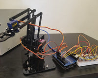
This project is a good starting point for anyone exploring multi-servo control for robotics or automation projects, such as a crane or a robotic arm for picking up simple items like cans or glass. It is well suited to hobbyists and students who want a hands-on introduction to driving several servos of different types and switching between manual control methods.
02 Hardware and Software Components
Gather everything below before you start. This is your checklist — names, models, and versions only.
Hardware Components
| Component | Description |
|---|---|
| 16-Channel 12-bit PWM/Servo Shield Servo Drive Module | Drives up to 16 servos over I2C using just 2 pins |
| SG90 Micro-Servo Motor | Small servo delivering roughly 0°–180° rotation |
| MG995 High Torque Servo Motor, Metal Gear (360° rotation) | Robust, low-power, continuous-rotation servo with metal gears |
| MG996R High-Torque Servo, Metal Gear | Metal gear servo with up to 11 kg/cm stall torque, 0°–180° rotation |
| Potentiometer | Three-terminal variable resistor used to provide an adjustable voltage/analog input |
| Joystick Module | Dual-axis analog input module with an integrated push button switch |
| Arduino Uno w/ cable | Microcontroller board (Robotdyn UNO, CH340G) running the control program |
| 5V 2A Power Supply AC-DC Wall Adapter | External power source for the servo shield |
| Large Tactile Push Button | Switch used to toggle between potentiometer and joystick control modes |
| Wires | Used for all component-to-board connections |
Software Tools
| Software | Version / Details |
|---|---|
| Arduino IDE | Used to write and upload the program |
03 Application Discussion
Here is what each component does and why it is part of this project.
16-Channel 12-bit PWM/Servo Shield Servo Drive Module

With just 2 pins, this 16-Channel 12-bit PWM/Servo Driver Shield can drive up to 16 servos over I2C. All 16 channels are driven simultaneously by the on-board PWM controller without needing further Arduino processing.
This I2C device (which makes use of the Wire library) can typically be shared or stacked with other I2C shields and devices — including numerous PWM/Servo Shields — so long as they all have distinct addresses. This shield's solder pads allow you to choose among 62 addresses (0x40–0x7E). Without solder jumpers, the default address is 0x40.
SG90 Micro-Servo Motor

The SG90 Servo Motor is an actuator that delivers a rotating motion roughly between 0° and 180°. The output shaft can only rotate 180 degrees because it is fastened to the potentiometer.
A small DC motor, plastic gears to boost torque, a potentiometer to indicate the output shaft's present position, and a control circuit make up the SG90 Servo Motor.
MG995 High Torque Servo Motor, Metal Gear (360° rotation)

The MG995 servo motor is a robust, dependable, and reasonably priced, low-power motor. Its twin shock-proof ball-bearing design has a metal gear, making industrial production quite doable. The motor responds and turns quickly, and it has a stable constant torque range with excellent holding power.
MG996R High-Torque Servo, Metal Gear

The MG996R is a metal gear servo motor with a maximum stall torque of 11 kg/cm. Like other RC servos, the motor rotates from 0 to 180 degrees depending on the duty cycle of the PWM signal given to its signal pin.
Potentiometer

A potentiometer, also known as a variable resistor or rheostat, is a three-terminal resistor with a sliding or revolving contact that creates a changeable voltage divider. If only one terminal, the wiper, is utilized, the potentiometer functions as a variable resistor.
Joystick Module

This module has two 5K potentiometers that are spring-loaded and have X and Y analog outputs that may be connected to analog inputs on the Arduino. If the cap is held down long enough to produce an audible click, a push button switch output is also available. Any digital input pin on the Arduino can be used to connect the pushbutton output.
04 Hardware Setup
Wire the components according to the schematic below.

Note that the PWM Servo Shield goes on top of the Robotdyn UNO. The servo shield requires an external power source as indicated in the schematic to power the servo motors (with 5V 2A DC power, you can connect 1–6 motors without experiencing power issues). The Robotdyn UNO also requires power for the chip to function.

Highlighted with the red arrow and circle above, the Robotdyn UNO has two extra analog pins that were utilized on top of the standard 6 analog pins. A4 and A5 pins can't be used for analog inputs since the SDA and SCL for I2C share the same pins. Therefore, when the Wire.h library is used, it utilizes A4 and A5 for the SDA and SCL pins, respectively.
05 Software Setup
Follow these steps in order. Do not skip any step.
Step 1 — Install the Arduino IDE
- Download and install the Arduino IDE from the official Arduino website.
- Connect the Arduino Uno (Robotdyn UNO) to your computer via USB cable.
Step 2 — Install Libraries
Install the following libraries before uploading the code:
- Pushbutton.h
- Adafruit_PWMServoDriver.h
- Wire.h (built-in Arduino library, no installation needed)
Step 3 — Upload the Code
- Copy the code from the Code section below into your Arduino IDE.
- Select the correct board and port for your Arduino Uno.
- Click Upload.
06 Code
Copy the file below into your Arduino IDE as described in the Software Setup section. Read the Code Breakdown section to understand what each part does.
servo_shield_control.ino
//Library Used
#include <Pushbutton.h>
#include <Adafruit_PWMServoDriver.h>
#include <Wire.h>

#define buttonPin 2 //Pin for the Button

Adafruit_PWMServoDriver pwm = Adafruit_PWMServoDriver(); //Servo Driver library initialization
Pushbutton pushButton(buttonPin); //Push Button library Initialization

#define SERVOMIN 150 //Minimum angle Value from the library
#define SERVOMAX 600 //Maximum angle Value from the library


uint8_t servoNum1 = 0, servoNum2 = 1, servoNum3 = 2; //Pins for the Servo in the Servo Shield

//Potentiometer pins
int potPin1 = A0, potPin2 = A1, potPin3 = A2;
//Potentiometer Value Storage
int potVal1, potVal2, potVal3;

//Joystick Pins
int joystickXPin = A6;
int joystickYPin = A7;
int joystick2XPin = A3;
//Joystick Value Storage
int joystickXVal, joystickYVal, joystick2XVal;

int counter = 0; //push button counter

void setup() {
    Serial.begin(9600); //Standard Serial interface initialization
    pwm.begin(); //Start the Servo Driver Library
    pwm.setPWMFreq(60); //Operating frequency of the Servo Shield & Servos
    Serial.println("Press the button to begin");
}

void loop() {
    //Code from the pushbutton library to read if the button is pressed and how many times it is pressed
    if (pushButton.isPressed()) {
        counter = counter + 1; //increase the counter once the button is released
        delay(350);
        //-------------------------------------Serial codes----------------------//
        if (counter == 1 || counter == 2) {
            Serial.print("Counter Value: ");
            Serial.println(counter);
            if (counter == 1) {
                Serial.println("Potentiometer Servo Controll");
                Serial.println(" ");
            }
            if (counter == 2) {
                Serial.println("Joystick Servo Controll");
                Serial.println(" ");
            }
        }
        if (counter == 3) {
            Serial.println("Counter Value: 1");
            Serial.println("Potentiometer Servo Controll");
            Serial.println(" ");
        }
        //-------------------------------------Serial codes----------------------//
    }
    //Reaction if the counter value is 1
    if (counter == 1) {
        potVal1 = analogRead(potPin1); //Reading the pin of the 1st potentiometer
        potVal1 = map(potVal1, 0, 1023, SERVOMIN, SERVOMAX); //Scaling the analog value into a readable value for the library
        pwm.setPWM(servoNum1, 0, potVal1); //Setting the Servo in pin 0 (servoNum1) to move according to the Scaled Value
        delay(15);

        potVal2 = analogRead(potPin2); //Reading the pin of the 2nd potentiometer
        potVal2 = map(potVal2, 0, 1023, SERVOMIN, SERVOMAX); //Scaling the analog value into a readable value for the library
        pwm.setPWM(servoNum2, 0, potVal2); //Setting the Servo in pin 1 (servoNum2) to move according to the Scaled Value
        delay(15);

        potVal3 = analogRead(potPin3); //Reading the pin of the 3rd potentiometer
        potVal3 = map(potVal3, 0, 1023, SERVOMIN, SERVOMAX); //Scaling the analog value into a readable value for the library
        pwm.setPWM(servoNum3, 0, potVal3); //Setting the Servo in pin 2 (servoNum3) to move according to the Scaled Value
        delay(15);
    }
    //Reaction if the counter value is 2
    if (counter == 2) {
        joystickXVal = analogRead(joystickXPin) ; //Reading the X axis pin of the joystick
        joystickXVal = map (joystickXVal, 0, 1023, SERVOMIN, SERVOMAX); //Scaling the analog value into a readable value for the library
        pwm.setPWM(servoNum1, 0, joystickXVal); //Setting the Servo in pin 0 (servoNum1) to move according to the Scaled Value
        delay(15);

        joystickYVal = analogRead(joystickYPin) ; //Reading the Y axis pin of the joystick
        joystickYVal = map (joystickYVal, 0, 1023, SERVOMIN, SERVOMAX); //Scaling the analog value into a readable value for the library
        pwm.setPWM(servoNum2, 0, joystickYVal); //Setting the Servo in pin 1 (servoNum2) to move according to the Scaled Value
        delay(15);

        forservoNum3(); //Calling the class for the servo number 3
    }
    //Reaction if counter is 3
    if (counter == 3) {
        counter = 1; //Go back to reaction #1
    }
}

void forservoNum3 () {
    joystick2XVal = analogRead(joystick2XPin) ; //Reading the X axis pin of the 2nd joystick
    joystick2XVal = map (joystick2XVal, 0, 1023, SERVOMIN, SERVOMAX); //Scaling the analog value into a readable value for the library

    //Code for the 360 continous servo to stop at a given scaled value
    if (joystick2XVal >= 360 && joystick2XVal <= 380) {
        joystick2XVal = 398;
        pwm.setPWM(servoNum3, 0, joystick2XVal); //Setting the Servo in pin 2 (servoNum3) to move according to the Scaled Value
        delay(15);
        joystick2XVal = analogRead(joystick2XPin) ; //Reading the X axis pin again to exit the IF function
        joystick2XVal = map (joystick2XVal, 0, 1023, SERVOMIN, SERVOMAX); //Scaling the analog value into a readable value for the library
    }
    else
        pwm.setPWM(servoNum3, 0, joystick2XVal); //Setting the Servo in pin 2 (servoNum3) to move according to the Scaled Value
    delay(15);
}
07 Code Breakdown
Here is what each part of the code does. Read this after uploading.
Libraries
| Library | Purpose |
|---|---|
| Pushbutton.h | Reads whether the push button has been pressed. Install from: github.com/pololu/pushbutton-arduino/blob/master/Pushbutton.h |
| Adafruit_PWMServoDriver.h | Controls the 16-Channel PWM/Servo Shield. Install from: github.com/adafruit/Adafruit-PWM-Servo-Driver-Library |
| Wire.h | Handles I2C communication between the Arduino and the servo shield. Built-in Arduino library. |
Key Functions
setup()
Starts serial communication, initializes the PWM driver, and sets the operating frequency to 60 Hz.
loop()
Checks if the push button has been pressed and increases a counter each time it is released. Depending on the counter value (1 or 2), it either reads the three potentiometers to drive the three servos, or reads the joystick X/Y values to drive servos 1 and 2 while calling forservoNum3() to drive servo 3. When the counter reaches 3, it resets back to 1.
forservoNum3()
Reads and scales the X axis value of the second joystick for servo 3, which is a continuous 360° servo (MG995). Because raw potentiometer readings are erratic at rest and cause the continuous servo to move randomly, this function checks whether the scaled reading falls within a specific range (360–380). If it does, the servo is held at a fixed "stop" value (398) instead of reacting to the noisy reading; otherwise, it drives the servo according to the scaled joystick value.
General Program Workflow
- On startup, the Arduino initializes the Serial interface and the PWM Servo Driver library and waits for the push button to be pressed.
- Pressing the button increases a counter that determines the active control mode: potentiometer control (counter = 1) or joystick control (counter = 2).
- In potentiometer mode, the three potentiometers each drive one servo by mapping their analog readings to the servo's PWM range.
- In joystick mode, the X and Y axes of the first joystick drive servos 1 and 2, while the second joystick's X axis drives servo 3 through the forservoNum3() stabilization function.
- Pressing the button a third time resets the counter back to potentiometer mode, and the cycle continues.
08 Testing and Calibration
After uploading, verify each of the following to confirm the system is working correctly.
Potentiometer Control Mode
With the counter set to 1, turning each potentiometer should smoothly move its corresponding servo across its range. The Serial Monitor should print "Potentiometer Servo Controll" after the first button press.
Joystick Control Mode
Pressing the button again should switch to joystick mode, printing "Joystick Servo Controll" on the Serial Monitor. Moving the first joystick's X and Y axes should move servos 1 and 2 accordingly, and moving the second joystick's X axis should move the continuous servo (servo 3).
09 System Demonstration
The video below shows the working system, demonstrating both the potentiometer and joystick control modes switching via the push button.
Video Demonstration
10 Conclusion
Building this project is without a doubt a fun and very good exercise for the brain in terms of problem solving. By learning how modules like the joystick module work, we can use them to control different types of servo motors, and we learned that the gear configuration of a servo makes it function differently from the others — some turn 360° continuously while others are limited to 180°. Controlling these servos with the map function, the servo shield, and its corresponding library made the work much easier and more convenient.
Possible Improvements and Future Enhancements
- Apply these controls to an actual robotics project, such as a crane or a robotic arm for picking up simple items such as cans or glass.
11 References
- Ampere Electronics MG996R Servo
-
Interface MG995 Servo Motor with Arduino – Example Code — by Microcontrollers Lab
https://microcontrollerslab.com/mg995-servo-motor-pinout-interfacing-with-arduino-features-examples/ -
Potentiometer — by Wikipedia contributors
https://en.wikipedia.org/wiki/Potentiometer
12 Project Authors
- Khient Bryan Medequillo
Quality Checked By:
- Kyla Jade Entorum
- Lemuel Jess Azaria