

Overview
This simple project involves creating a laser trip wire using an Arduino UNO. It integrates a laser module as its light source and an LDR module as its trigger, using an LCD module to provide real time sensor status and visual feedback. The text displayed on the LCD cycles between “INTRUDER ALERT", “TRIPWIRE ACTIVATED" and "MONITORING: BEAM INTACT” monitoring states.
Hardware Used
- Arduino Uno with USB Cable
- Breadboard
- Laser Module
- LDR Light Sensor Module
- Passive Buzzer Module 5V
- 14500 Li-ion Battery 3.7V/1200mAh
- LCD Module 16x02 with i2C
- Jumper Wires
- 2x Battery Holder 14500 with Knife/Switch
Software Use
- Arduino IDE
Application Discussion
- Arduino Uno R3
We're using an Arduino Uno as the main microcontroller for this project. It is a popular open-source microcontroller board based on the ATmega328P microcontroller.
- Laser Module (KY – 008)

Pinout:
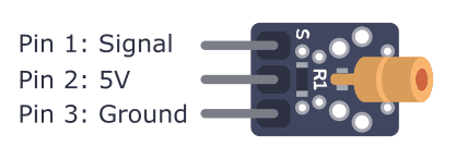
The KY‑008 is a compact, low-cost red laser transmitter module which integrates a 650 nm red laser diode, a current-limiting resistor, and three male header pins on a PCB. Designed for easy interfacing with Arduino, ESP32, Raspberry Pi, and similar, it's ideal for simple laser pointer functions, optical communication, or creating laser tripwire setups. Handle with care—never point the laser at eyes or reflective surfaces.
Specifications:
|
Feature |
Specification |
|
Laser Wavelength |
650 nm (red beam) |
|
Output Power |
≤ 5 mW (Class IIIa/3A laser) |
|
Operating Voltage |
5 V (some sources suggest 3–5 V) |
|
Operating Current |
~30–40 mA |
|
Temperature Range |
−10 °C to +40 °C |
|
Module Size |
~18.5 × 15 mm (PCB); some list 15 × 24 mm |
|
Heat & Regulation |
Simple resistor-based current limiting; may heat under long operation |
-
LDR Light Sensor Module
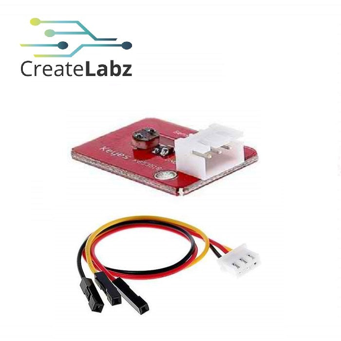
Pinout:
VCC – 5V
GND – GND
OUT – Signal output
The K853518 is a classic analog light sensor module based on a Light Dependent Resistor (LDR). It uses a simple voltage divider circuit and outputs a voltage proportional to ambient light levels. Ideal for Arduino, ESP32, Raspberry Pi Pico (with external ADC), etc.
Key Specifications
- Operating Voltage: 3.0 – 5.5 V DC
- Output Type: Analog voltage (direct output)
- Layout & Dimensions: PCB with two mounting holes (~3 mm); board size ≈ 29 × 21 × 9.5 mm; weight ~2 g
- Analog Range: Voltage varies linearly with light—higher in bright, lower in dark
- LDR Characteristics (typical for similar modules): Dark ≈ 50 kΩ → Bright < 500 Ω
- Signal Cable: 20 cm 3-wire cable included (VCC, GND, OUT)
-
Passive Buzzer Module 5V (FC – 07)

Pinout:
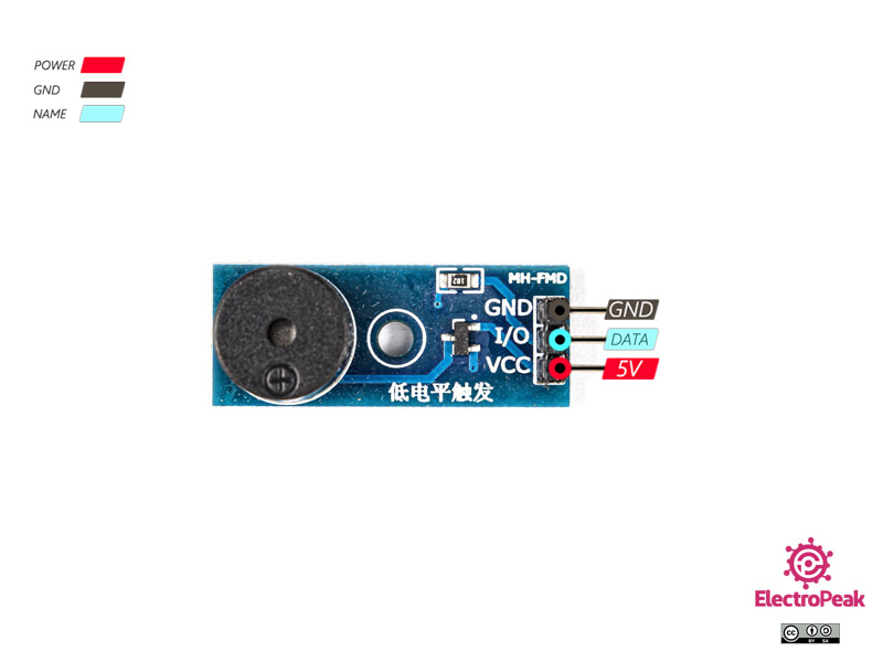
A compact PWM-driven sound module using a passive piezo buzzer. Requires a microcontroller to send square-wave signals (2–5 kHz typically) to produce sounds like tones or melodies. It doesn't buzz with steady DC voltage—only with oscillating signals.
Key Specifications
|
Feature |
Details |
|
Operating Voltage |
3.3–5 V DC |
|
Rated Current |
< 30 mA typical |
|
Drive Signal Frequency |
PWM square‑wave, ~1.5–5 kHz (resonant freq ≈2.5 kHz) |
|
Sound Level |
≥ 85 dB @ 10 cm |
|
PCB Size |
~20 × 20 mm (some ~33 × 13 × 10 mm) |
|
Weight |
~3 g |
|
Modules Includes |
Often includes LED indicator, S8550 driver transistor, and a 3‑pin cable |
-
LCD Module 16x02 with i2C
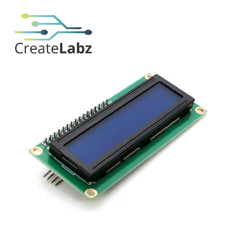
Pinout:

This module combines a standard 16×2 character LCD (HD44780-compatible) with an I2C “backpack” module, drastically simplifying wiring—just four wires: VCC, GND, SDA, and SCL. It’s ideal for microcontrollers like Arduino, ESP32, Raspberry Pi, and more.
Hardware Setup![]()
Wiring Diagram:

Procedure: Step-by-Step Build Guide
Step 1: Gather Your Components
- Arduino Uno
- Laser Module (KY-008)
- LDR Sensor (KY-018 or Keyes K853518)
- 10kΩ resistor
- Passive Buzzer (FC-07)
- Push Button
- LCD 16x2 with I2C module
- Breadboard
- Jumper wires (male-to-male)
- 5V battery pack or USB power bank
- USB cable (if using power bank)
Step 2: Power Setup
- If using a USB power bank:
- Plug the USB cable into the Arduino’s USB port.
- This powers the Arduino and the 5V rail safely.
- If using a 5V battery pack with open wires:
- Connect Battery + (red) to Arduino 5V pin
- Connect Battery – (black) to Arduino GND pin
- On the breadboard, connect:
- Arduino 5V → red power rail
- Arduino GND → blue ground rail
Step 3: Wire the LCD (I2C 16x2)
|
LCD Pin |
Connect To |
|
VCC |
Breadboard 5V |
|
GND |
Breadboard GND |
|
SDA |
Arduino A4 |
|
SCL |
Arduino A5 |
Step 4: Wire the Laser Module (KY-008)
|
Laser Pin |
Connect To |
|
VCC |
Breadboard 5V |
|
GND |
Breadboard GND |
|
Signal |
Arduino D9 (LASER_PIN) |
Step 5: Wire the LDR + 10kΩ Resistor (Voltage Divider)
- Place LDR across two breadboard rows.
- Connect:
- One LDR leg → Breadboard 5V rail
- Other LDR leg → Arduino A0 (LDR_PIN) AND one end of a 10kΩ resistor.
- Other end of the resistor → Breadboard GND rail
Step 6: Wire the Passive Buzzer (FC-07)
|
Buzzer Pin |
Connect To |
|
VCC |
Breadboard 5V |
|
GND |
Breadboard GND |
|
Signal |
Arduino D8 (BUZZER_PIN) |
Step 7: Wire the Push Button
- Connect one leg of the push button → Arduino D6 (BUTTON_PIN)
- Connect the other leg → Breadboard GND rail
- (No need for an external resistor — INPUT_PULLUP is enabled in code.)
Step 8: Upload the Code
- Open Arduino IDE.
- Paste your provided sketch.
- Make sure LiquidCrystal_I2C library is installed.
- Connect Arduino to PC and upload the sketch.
Step 9: Test and Calibrate
- Power up the system using your battery pack or USB power bank.
- The LCD should display "System Ready".
- Aim the laser beam directly at the LDR.
- When the beam is blocked, the buzzer should sound, and LCD should say "INTRUDER ALERT".
- Press the button to reset the system.
Step 10: Enclosure Building
· Drill holes and follow the initial plan for the enclosure use nonconductive adhesive to build the device with the enclosure provided.
Optional Tweaks
- Adjust LDR_THRESHOLD if too sensitive or not triggering.
Software Setup
- This is the Arduino sketch use for the project:
Code Breakdown
Library Used:
- #include <LiquidCrystal_I2C.h> - We used the LiquidCrystal I2C by Frank de Brabander
LDR (Light Dependent Resistor) Setup:
#define LDR_PIN A0
#define LDR_THRESHOLD 600
- LDR_PIN A0: Reads the laser status through the LDR.
- LDR_THRESHOLD 600: If the LDR value drops below this threshold, it means the laser beam is broken.
Laser Setup:
#define LASER_PIN 9
- LASER_PIN 9: Activates the laser to form the tripwire.
Button Setup (for Reset):
#define BUTTON_PIN 7
- BUTTON_PIN 7: Detects button press to reset the system after an alert.
Button Debounce Logic:
if ((millis() - lastDebounceTime) > DEBOUNCE_DELAY) {
if (reading == LOW && !buttonPressed) {
buttonPressed = true;
if (alertTriggered) {
noTone(BUZZER_PIN); // Stop buzzer
alertTriggered = false; // Reset alert
lcd.clear();
lcd.print("System Reset");
delay(2000); // Pause before resuming
lcd.clear();
}
}
}
- Button Debounce: Ensures stable button press detection, and resets the alert when pressed.
Laser Beam Break (Intruder Detection):
if (ldrValue < LDR_THRESHOLD && !alertTriggered) {
alertTriggered = true;
tone(BUZZER_PIN, 1000); // Start buzzer
lcd.clear();
lcd.print("!!! ALERT !!!");
lcd.print("INTRUDER ALERT");
}
- Intruder Detection: If the laser beam is broken, it triggers an alert by sounding the buzzer and showing the message on the LCD.
Normal Monitoring:
if (!alertTriggered) {
lcd.setCursor(0, 0);
lcd.print("Monitoring...");
lcd.print("Beam Intact");
}
- Normal Monitoring: If no alert is triggered (beam intact), the system displays "Monitoring..." on the LCD.
Testing and Calibration
- Test the device by triggering the laser module so that the LDR will trigger as well and the buzzer will turn on and pressed the button for resetting the device.
-
Adjust the code if necessary for compacting all the components in an enclosure box.
Final Adjustments
- If the device is working properly, we can add the enclosure box for real-world deployment and for clean and tidy circuit and wire management.
-
Adjust LDR_THRESHOLD if too sensitive or not triggering
Optional Tweaks
- Make a PCB out of it for permanent and neat wiring for stable device performance.
Video Demonstration
Conclusion
In conclusion, this Laser Tripwire Box project using the Arduino Uno, Laser Module, and OLED display offers a practical and interactive way to develop essential skills in microcontroller programming, sensor interfacing, and real-time alert systems. This project demonstrates how simple components like a laser and a light sensor can be combined with an OLED display to create an effective intrusion detection system. It provides valuable experience in building security-focused electronics, blending hardware and software to design a reliable and user-friendly solution. Through this project, you’ll enhance your problem-solving abilities, gain a deeper understanding of embedded systems, and explore practical applications in home security and monitoring—making it an ideal introduction to IoT and smart security solutions.
References
- Arduino Uno Official Guide
- Laser Module & Light Sensor Tutorials
- OLED Display Integration with Arduino
- Basic Security System Projects with Arduino
Authors (Capacitrio)
- Mark A. Macahig
- Knile Angelo B. Diez
- Kent Lawrence M. Escobar


