

Overview:
Switch your lights ON/OFF with only the temperature of your surroundings! This blog post teaches you how to control a light source (LED lights) depending on the measured surrounding temperature. The temperature reading will also be displayed using an I2C LCD display, while all of these are managed by the Arduino Uno Microcontroller.
Hardware and Software Components:
Hardware:
Software:
Application Discussion:
-
DS18B20 Temperature Sensor

- The DS18B20 communicates over a 1-Wire bus that by definition requires only one data line (and ground) for communication with a central microprocessor.
- Measures Temperatures from -55°C to +125°C (-67°F to +257°F)
- ±0.5°C Accuracy from -10°C to +85°C
- The sensor needs a 10k ohm (pull-up) resistor between the data and the power supply for efficient temperature conversion.
- The Arduino libraries; DallasTemperatures(DS18B20 support for Arduino) and OneWire(Read data from 1-wired devices) are needed to connect with the Arduino UNO.
1-Wire is a powerful bus system that is particularly appreciated for its simple design and energy saving. energy saving. The bus participants are controlled by a master. Multiple slaves are accessed using only 2-wires in this interface type. Due to use of less wires, the interface is cheaper, easy to implement, and supports longer distance (about 300 meters).


Analog sensor senses the external parameters (wind speed, solar radiation, light intensity etc.) and gives analog voltage as an output. The output voltage may be in the range of 0 to 5V. Logic High is treated as “1” (3.5 to 5V) and Logic Low is indicated by “0” (0 to 3.5 V). Digital Sensor on the other hand, produces discrete values (0 and 1’s). Discrete values often called digital (binary) signals in digital communication. These are some of the characteristics between the two: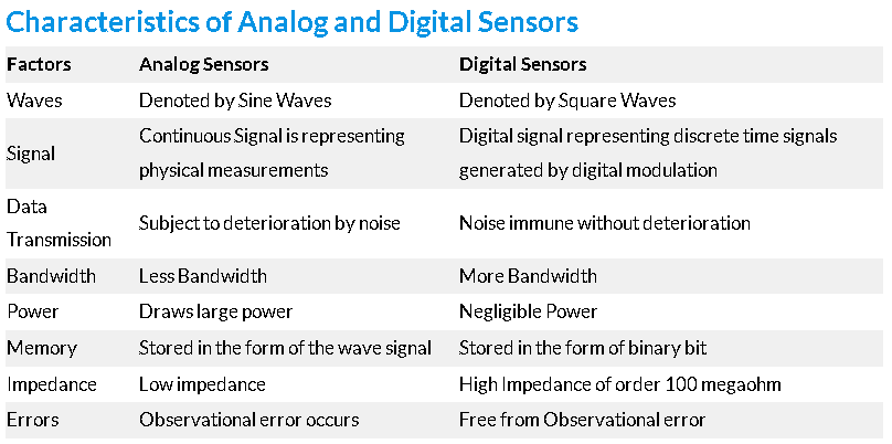
Overall, digital sensors are introduced to cater the drawbacks of analog sensors.
-
1602 LCD (Liquid Crystal Display) with I2C module

- This LCD is very cheap and widely available, and is an essential part for any project that displays information
- It uses the I2C (Inter-Integrated Circuit) communication protocol
- The real significant advantage of this I2C LCD module will simplify the circuit connection, save some I/O pins on Arduino board, and simplified firmware development with widely available Arduino library
- Robotdyn Arduino Uno R3 (Compatible) CH340G USB-serial
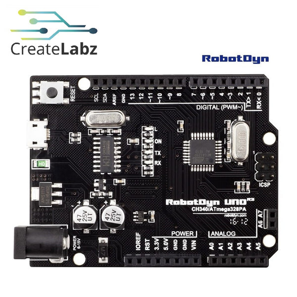
- The Arduino-compatible Uno R3 CH340 board differs from the official Arduino UNO R3 board in that it does not use the expensive FTDI USB-to-serial driver chip
- Instead, it features the CH340 USB-to-serial converter chip which makes it low cost and 100% Arduino compatible
Hardware Set-up:
Schematic Diagram:

Connections:
Arduino Uno R3

- The Arduino provides a 5V power supply for the project and will serve as the VCC (positive voltage supply) pin, together with GND (ground - negative supply) pin.
DS18B20 Temperature Sensor

- It consists of 3 wires; GND, VCC, and DQ (Digital Input/Output)
- VCC and DQ must be connected with a 10k ohm resistor (pull-up resistor) to function properly
- DATA is connected to pin 7 to input temperature values

- The I2C pins are used to connect the LCD to the Arduino
- The pins are as follow; GND, VCC, SDA (Data Line), SCL (Clock Line)
- SDA pin must be connected to pin A4 (Uno R3 default)
- SCL pin must be connected to pin A5 (Uno R3 default)
Software Set-up:
Code:
//INCLUDE LIBRARIES
#include <OneWire.h>
#include <DallasTemperature.h>
#include <Wire.h>
#include <LiquidCrystal_I2C.h>

//DEFINE SENSOR PIN
#define ds18b20 7 //pin 7

//DEFINE LED PINS
#define yellow 9 //pin 9
#define red 10 //pin 10

//COMPONENT VARIABLES
OneWire busWire(ds18b20);
DallasTemperature tempSensor(&busWire);
LiquidCrystal_I2C lcd(0x27,16,2);

//VARIABLES
float temperature = 0;

//SET-UP CODE (ONCE)
void setup() {
  //start sensor
  tempSensor.begin();

  //start serial monitor
  Serial.begin(9600);

  //start lcd
  lcd.init();

  //lcd backlight on
  lcd.backlight();

  //execute when serial monitor not opened
  while(!Serial)

  //set led as output
  pinMode(yellow,OUTPUT);
  pinMode(red,OUTPUT);
}

//MAIN CODE (LOOP)
void loop() {
  //initially turns off all led at start
  digitalWrite(yellow,LOW);
  digitalWrite(red,LOW);

  //generate temperature readings from the sensor
  tempSensor.requestTemperatures();

  //gets the temperature reading (C) in the first index (0), and set is as a float value (with decimal)
  temperature = tempSensor.getTempCByIndex(0);

  //display values in serial monitor
  Serial.print("Temperature: ");
  Serial.print(temperature);
  Serial.println(" C");

  //display values in lcd
  lcd.clear(); //clear past values
  lcd.setCursor(0,0); //first line in lcd
  lcd.print("Temp: ");
  lcd.print(temperature);//temperature float value
  lcd.print(" C");

  //led trigger arguments
  if(temperature < 27){
    digitalWrite(yellow,HIGH); //turn on yellow led
    lcd.setCursor(0,1); //second line in lcd
    lcd.print("Status: COLD"); //cold temperature reading
  }else if(temperature >= 27 && temperature < 37){
    lcd.setCursor(0,1);
    lcd.print("Status: NORMAL"); //normal temperature reading
  }else if(temperature >= 37){
    digitalWrite(red,HIGH); //turn on red led
    lcd.setCursor(0,1);
    lcd.print("Status: HOT"); //hot temperature reading
  }

  //1 second delay
  delay(1000);
}
Code Breakdown:
Libraries:
- OneWire.h
- Access 1-wire temperature sensors, memory and other chips.
- Can be downloaded on the Arduino Library Manager or on the website
- DallasTemperature.h
-
Arduino Library for Dallas Temperature ICs
Supports DS18B20, DS18S20, DS1822, DS1820 - Can be downloaded on the Arduino Library Manager or on the website
- Wire.h
- This library allows you to communicate with I2C/TWI devices
- LiquidCrystal_I2C.h
- The library allows to control I2C displays with functions extremely similar to LiquidCrystal library.
Variables:
- OneWire busWire(ds18b20);
- Sets pin 7 where the bus wire of the DS18B20 as data input
- DallasTemperature tempSensor(&busWire);
- Sets buswire pin 7 for reading temperature values
- LiquidCrystal_I2C lcd(0x27,16,2);
- Identifies the lcd used in the project
- 0x27 is the default slave address of the 1602 lcd
- 16 characters per line
- 2 line display
Functions:
- tempSensor.requestTemperatures();
- A function of DallasTemperature library. Fetch the current data reading from the sensor.
- tempSensor.getTempCByIndex(0);
- Also a function of the said library. Since the sensor fetches many readings, the first reading, index (0) will be prioritized and set as the current temperature reading to be projected.
Video Demo:
Conclusion:
We conclude that the DS18B20 Temperature Sensor is preferably one of the easiest to use and configure since it is a 1-wire sensor and also waterproof. It features a long wire so that it can be used for outdoor temperature sensing. You shouldn't worry for signal degradation in long distance measuring since it is a digital, but the most important is that it is cheap and easily accessible!
I also recommend to replace the LEDs with a relay - controlled light bulb for a more advanced practice.
References:
- https://datasheets.maximintegrated.com/en/ds/DS18B20.pdf
- https://www.rfwireless-world.com/Terminology/Advantages-and-Disadvantages-of-1-wire-interface.html
- https://learn.sparkfun.com/tutorials/pull-up-resistors/all
- https://shop.elabnet.de/en/info/1-wire
- https://www.researchgate.net/figure/1-Wire-Bus-Interface-Circuitry-4-p10_fig2_252220957
- https://www.codrey.com/electronics/different-types-of-sensors/
- https://iot4beginners.com/analog-sensors-vs-digital-sensors/
- http://www.handsontec.com/dataspecs/module/I2C_1602_LCD.pdf
- Arduino Uno R3 CH340 Board with USB Cable – Art of Circuits
- https://datasheets.maximintegrated.com/en/ds/DS18B20.pdf
- https://www.rfwireless-world.com/Terminology/Advantages-and-Disadvantages-of-1-wire-interface.html
- https://learn.sparkfun.com/tutorials/pull-up-resistors/all
- https://shop.elabnet.de/en/info/1-wire
- https://www.researchgate.net/figure/1-Wire-Bus-Interface-Circuitry-4-p10_fig2_252220957
- http://www.handsontec.com/dataspecs/module/I2C_1602_LCD.pdf
- Arduino Uno R3 CH340 Board with USB Cable – Art of Circuits


