
RFID Attendance System with Real-Time Data Storage to Google Spreadsheets
01 Overview
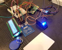
This project is an attendance system using RFID tags/stickers to communicate with an MFRC522 RFID Reader/Writer Module connected to an Arduino UNO. The authentication data received by the Arduino UNO is then transmitted to Google Spreadsheets through an ENC28J60 Ethernet Module for real-time data storage and access. This makes the attendance system paperless and organized, thanks to the timestamp, card key, and username columns kept through the spreadsheet API.
Project Use Case
This project fits schools, offices, or small organizations that want a simple, low-cost tap-to-log attendance system without buying commercial hardware, and it's also a solid introduction to combining RFID authentication with cloud-based logging through a spreadsheet.
02 Hardware and Software Components
Gather everything below before you start. This is your checklist — names, models, and versions only.
Hardware Components
| Component | Description |
|---|---|
| 13.56MHz MFRC522 RFID Reader/Writer Module (RobotDyn) | Reads the RFID/NFC tag's card key when it's tapped near the reader. |
| RFID/NFC Tags | Carries the unique card key that identifies each user. |
| ENC28J60 Ethernet Module (RobotDyn) | Gives the Arduino a wired internet connection to relay attendance data online. |
| Arduino UNO with USB Cable | Runs the sketch, reads the RFID module, and controls the Ethernet module. |
| Breadboard | Used to prototype the wiring between the modules and the Arduino. |
| Jumper Wires (Male-to-Male and Male-to-Female) | Used to wire the RFID and Ethernet modules to the Arduino. |
Software Tools
| Software | Details |
|---|---|
| Arduino IDE | Used to write and upload the sketch to the Arduino UNO. |
| PushingBox API | Relays the GET request from the Arduino to the Google Script web app. |
| Google Spreadsheets | Stores the timestamp, card key, and username data. |
| Google Script (inside Google Spreadsheets) | Receives the incoming data and writes it into the spreadsheet. |
03 Application Discussion
Here is what each component does and why it is part of this project.
How Does an RFID Reader/Writer Module Work?
An RFID (Radio-Frequency Identification) system consists of two main components: a transponder, or tag, located on the object to be identified, and a transceiver, or reader.
The RFID reader consists of a radio frequency module, a control unit, and an antenna coil that generates a high-frequency electromagnetic field. The tag, on the other hand, is usually passive, consisting of just an antenna and an electronic microchip. When it gets near the reader's electromagnetic field, induction generates a voltage in its antenna coil, and that voltage powers the microchip.
Technical Details: MFRC522 Reader/Writer Module (RobotDyn)
| Specification | Value |
|---|---|
| Compatibility | Reads and writes Mifare tags, including MF1xxS20, MF1xxS70, and MF1xxS50 |
| Frequency | 13.56MHz electromagnetic field |
| Transfer Speed | Up to 848 kBd in both directions |
| Size | 36 x 36mm |
| Power | 3.3V or 5V |
| Antenna | Built-in |
| Sensitivity Range | Up to 25mm |
Once the tag is powered, it can extract the transmitted message from the reader. To send a message back, it uses a technique called load manipulation: switching a load at the tag's antenna on and off affects the power consumption of the reader's antenna, which is measured as a voltage drop. These voltage changes are captured as ones and zeros, and that's how data travels from the tag to the reader.
Another method of transferring data between the tag and reader is backscattered coupling, where the tag uses part of the received power to generate another electromagnetic field that the reader's antenna picks up.
How Does an ENC28J60 Module Work?
The ENC28J60 is a chip developed by Microchip. It has 28 pins and contains a complete stand-alone Ethernet controller for a 10BASE-T network connection, with an SPI interface so microcontrollers like the Arduino can communicate with it.
10BASE-T is the same connector type found on many computers to connect to a network by wire, where "10" indicates a maximum speed of 10 Mbit/sec. That's slow by modern standards, but it's plenty for a device like the Arduino.
Technical Details: ENC28J60 Ethernet Module (RobotDyn)
| Specification | Value |
|---|---|
| Type | 10BASE-T stand-alone Ethernet module with on-board MAC and PHY |
| Buffer RAM | 8 kBytes |
| Interface | SPI serial interface, works with 3.3V and 5V logic |
| Target Applications | VoIP, industrial automation, building automation, home control, security, and instrumentation |
04 Hardware Setup
Wire the components to the board using the tables below.
MFRC522 RFID Module to Arduino
| RFID Pin | Arduino Pin | Description |
|---|---|---|
| SDA / SS | Pin 9 | Slave select for the RFID module |
| SCK | Pin 13 | Shared SPI clock |
| MOSI | Pin 11 | Shared SPI data out |
| MISO | Pin 12 | Shared SPI data in |
| RST | Pin 8 | Reset pin |
| GND | GND | Ground |
| 3.3V | 3.3V | Power |
ENC28J60 Ethernet Module to Arduino
| Ethernet Pin | Arduino Pin | Description |
|---|---|---|
| CS | Pin 10 | Slave select for the Ethernet module |
| SCK | Pin 13 | Shared SPI clock |
| SI | Pin 11 | Shared SPI data in |
| SO | Pin 12 | Shared SPI data out |
| GND | GND | Ground (both GND pins on the module) |
| VCC | 3.3V or 5V | Power, depending on the module's supported voltage |
Assembly Notes
Both the RFID and Ethernet modules communicate over SPI, so they share pins 11 to 13 (MOSI, MISO, and SCK). Since only one SPI device can be active at a time, each module needs its own Chip Select pin: the Ethernet module uses pin 10, and the RFID module uses pin 9. Setting a CS pin LOW with digitalWrite() activates that device, and you must disable one before enabling the other. In this project, the RFID module is enabled first to read and store the card key, then it's disabled while the Ethernet module is enabled to relay the data to the spreadsheet.
05 Software Setup
The setup runs in this order: Google Spreadsheets and Google Script setup, PushingBox API setup, then Arduino IDE setup. Don't skip ahead if a step isn't working, since each stage depends on the one before it.
Step 1 — Google Spreadsheets and Google Script Setup
- Log in to your Google account and open sheets.google.com.
- Create a new spreadsheet, rename it, and add three column labels: Timestamp, Card Key, and Username.
- In the tabs above the document, click Tools, then Script Editor. Copy and paste the Google Script code from Section 06 (the language used is JavaScript). If you add another column to the spreadsheet, add a matching switch case statement in the script, copying the syntax of an existing case and renaming the case name and rowData value.
- Go back to your spreadsheet document to get the Spreadsheet ID, then paste it between the apostrophes in the script's
var id = 'place your spreadsheet ID here';line.
- In the Script Editor, click File, then Save, and rename your project.
- Click Publish, then Deploy as web app. Set "Who has access to the app" to "Anyone, even anonymous," and click Deploy.
- When prompted for authorization, click Review Permissions, choose your Google account, then click Advanced, "Go to <file name> (unsafe)," and Allow.
- Before clicking OK, copy the web app URL, then click OK. Save that URL somewhere for the next steps.
- Test the script by adding a query like
?ID=John Smithafter "exec" in the web app URL, then open the full URL in your browser (add %20 in place of spaces if needed).
- The webpage should show "Ok," and the spreadsheet should now show the sample entry. If the timestamp doesn't display correctly, go to Format, then Number, then Date time.
Step 2 — PushingBox API Setup
- Go to www.pushingbox.com and click Login with Google.
- Click My Services, then Add A Service, scroll down, and click Select This Service beside CustomURL.
- Name your CustomURL configuration, paste your Google Script web app URL into the Root URL field, and click Submit.
- Click My Scenarios. Under "Add a Device or Scenario," name your scenario and click Add.
- Click Add an Action, then click Add an action with this service beside the scenario you just created.
- In the Data field, enter the data format matching the parameters your Google Script expects (for example,
ID), then click Submit.
- Sample-test your API by sending a GET request in this format, using your own Device ID (found on the scenario's Update page):
api.pushingbox.com/pushingbox?devid=<pasteYourDeviceIDhere>&ID=<sampleNameforID>For example:
api.pushingbox.com/pushingbox?devid=v8A9EF9B06CC352B&ID=Pocahontas- Paste that into your browser. It should post the sample data into your spreadsheet.
Step 3 — Arduino IDE Setup
- Copy the Arduino code from Section 06 into your IDE.
- Get your computer's MAC address (see below), and paste it into the sketch's
static byte mymac[]array.
For Mac Users
Connect your Mac's ethernet port to your router's LAN port using a UTP cable. Go to System Preferences, then Network, click Ethernet on the left, then Advanced, then the Hardware tab, where you'll see the MAC address. For example, if your MAC address is 10:a1:b1:ad:66:df, format it in the sketch as:
static byte mymac[] = {0x10,0xa1,0xb1,0xad,0x66,0xdf}; // Be sure this address is unique in your networkFor Windows Users
Connect your PC's ethernet port to your router's LAN port using a UTP cable. Click the network icon in the taskbar, then Network & Internet Settings, then View Your Network Properties in the Status tab. Find the property named Ethernet and copy its Physical Address (MAC), formatting it the same way as above.
- Paste your PushingBox Device ID into the
<insertPushingBoxdevIDhere>placeholders in the sketch (remove the angle brackets). - Press Upload, then tap your NFC/RFID tag. A sample serial monitor output will appear, similar to the one shown in Section 09.
06 Code
Copy each file below into the correct place as described in the Software Setup section. Read the Code Breakdown section to understand what each part does.
Google Script Code (Code.gs)
//-----------------------------------------------
//Originally published by Mogsdad@Stackoverflow
//Modified for jarkomdityaz.appspot.com
//-----------------------------------------------
/*

GET request query:
<paste your web app URL here>

Pushingbox link:
<paste your Pushingbox link here>

*/

/* Using spreadsheet API */

function doGet(e) {
  Logger.log( JSON.stringify(e) );  // view parameters

  var result = 'Ok'; // assume success

  if (e.parameter == undefined) {
    result = 'No Parameters';
  }
  else {
    var id = 'paste your spreadsheet ID here'; // Spreadsheet ID
    var sheet = SpreadsheetApp.openById(id).getActiveSheet();
    var newRow = sheet.getLastRow() + 1;
    var rowData = [];
    //var waktu = new Date();
    rowData[0] = new Date(); // Timestamp in column A
    for (var param in e.parameter) {
      Logger.log('In for loop, param='+param);
      var value = stripQuotes(e.parameter[param]);
      Logger.log(param + ':' + e.parameter[param]);
      switch (param) {
        case 'ID': //ID
          rowData[1] = value; //Value in column B
          break;
        default:
          result = "unsupported parameter";
      }
    }
    Logger.log(JSON.stringify(rowData));

    // Write new row below
    var newRange = sheet.getRange(newRow, 1, 1, rowData.length);
    newRange.setValues([rowData]);
  }

  // Return result of operation
  return ContentService.createTextOutput(result);
}

/**
* Remove leading and trailing single or double quotes
*/
function stripQuotes( value ) {
  return value.replace(/^["']|['"]$/g, "");
}
rfid_attendance.ino
////
//
// General code from http://www.pushingbox.com for Arduino + Ethernet Shield/Module (ENC28J60)
// Library EtherCard from https://github.com/jcw/ethercard is under mit license
//
////
#include <EtherCard.h>
#include <SPI.h>
#include <MFRC522.h>

  /////////////////
 // MODIFY HERE //
/////////////////
static byte mymac[] = {paste mac address here};   // Be sure this address is unique in your network

// Debug mode
boolean DEBUG = true;
  ///////
 //End//
///////


const char website[] PROGMEM = "api.pushingbox.com";
byte Ethernet::buffer[400]; //change the value within the range of 300 to 850 for faster connection

#define rfidCSpin 9 //CS pin for MFRC522 RFID module
#define etherCSpin 10 //CS Pin for ENC28J60 Module
#define RST_PIN 8 //Reset pin

MFRC522 rfid (rfidCSpin, RST_PIN);
MFRC522 :: MIFARE_Key key;

String data ; //GET query with data
String ID;

void setup () {
  Serial.begin(9600);
  //pinMode(pinDevid1, INPUT);
  SPI.begin();
  rfid.PCD_Init();

  //disable RFID
  pinMode(9, OUTPUT);
  digitalWrite(9, HIGH);

  //enable ethernet
  pinMode(10, OUTPUT);
  digitalWrite(10, LOW);


}

void loop () {

    ether.packetLoop(ether.packetReceive());

    if (! rfid.PICC_IsNewCardPresent () ||! rfid.PICC_ReadCardSerial ())
    return ;

    digitalWrite(10, HIGH); //turn off ethernet
    digitalWrite(9, LOW); //turn on RFID

    if (digitalRead(rfidCSpin) == LOW && digitalRead(etherCSpin) == HIGH){
      //Serial.println("Scan NFC tag.");
      rfidDetect(); //detects the validity of the NFC/RFID tags
      storeKey();//if validated, stores card key into a string
      delay(10);
    }
    delay(50);

      digitalWrite(9, HIGH); //turn off RFID
      digitalWrite(10, LOW); //turn on ethernet
      connectEthernet(); //connects ethernet module to your router

      //if-else statements that will determine what URL to open
      if (ID == "Eddyson Canoy"){
        const char x[] PROGMEM = "<insertPushingBoxdevIDhere>&ID=Eddyson%20Canoy";
        ether.browseUrl(PSTR("/pushingbox?devid="), x, website, my_callback);
        ID = "";
      }
      else if (ID == "Mikko Alinsub"){
        const char y[] PROGMEM = "<insertPushingBoxdevIDhere>&ID=Mikko%20Alinsub";
        ether.browseUrl(PSTR("/pushingbox?devid="), y, website, my_callback);
        ID = "";
      }
      else {
        Serial.println("Can't store data to online server");
      }


}

// called when the client request is complete
static void my_callback (byte status, word off, word len) {
  Serial.println(">>>");
  Ethernet::buffer[off+300] = 0;
  Serial.print((const char*) Ethernet::buffer + off);
  Serial.println("...");
  Serial.println("-------------");
  Serial.println("Tap card key.");
}
void storeKey(){
  String strID = "";
  for (byte i = 0; i < 4; i ++) {
    strID +=
    (rfid.uid.uidByte [i] < 0x10 ? "0" : "" ) +
    String (rfid.uid.uidByte [i], HEX) + (i!=3 ? ":" : "" );
    //Serial.println(strID);
    delay(10);
  }
  strID.toUpperCase ();

  // At this point, the strID variable will store the UID of the tag.
  Serial.print ( "Card key: " );
  Serial.println (strID);


  if(strID == "F1:95:B2:01"){ //replace the strID depending on the NFC/RFID tag's card key
     ID = "insert Employee 1 name here";
     Serial.println(ID);
     }
  else if (strID == "F1:8E:B2:01"){ //replace the strID depending on the NFC/RFID tag's card key
     ID = "insert Employee 2 name here";
     Serial.println(ID);
    }
  else{
     Serial.println("ID not recognized.");
    }
  rfid.PICC_HaltA ();
  rfid.PCD_StopCrypto1 ();
}
void rfidDetect(){
  // Serial.print (F ("PICC type:"));
  MFRC522 :: PICC_Type piccType = rfid.PICC_GetType (rfid.uid.sak);
  // Serial.println (rfid.PICC_GetTypeName (piccType));

  // Check is the PICC of Classic MIFARE type
  if (piccType != MFRC522 :: PICC_TYPE_MIFARE_MINI && piccType != MFRC522 :: PICC_TYPE_MIFARE_1K && piccType != MFRC522 :: PICC_TYPE_MIFARE_4K) {
    Serial.println( "Your tag is not of type MIFARE Classic." );
    return ;
  }
}
void connectEthernet(){
  if(DEBUG){Serial.println("\n[getDHCPandDNS]");}

  //
  //***Depending of your Shield, you may have to try this line instead of the second***//
  //if(ether.begin(sizeof Ethernet::buffer, mymac) == 0)
  if(ether.begin(sizeof Ethernet::buffer, mymac, 10) == 0)//pin 10 is the CS pin for ethernet
    if(DEBUG){Serial.println( "Failed to access Ethernet controller");}

  // Wait until we have an IP from the DHCP
  while(!ether.dhcpSetup()){
    if(DEBUG){Serial.println("Error: DHCP failed. Can't get an IP address, let's retry...");}
  }

  if(DEBUG){
    ether.printIp("My IP: ", ether.myip);
    ether.printIp("Netmask: ", ether.netmask);
    ether.printIp("GW IP: ", ether.gwip);
    ether.printIp("DNS IP: ", ether.dnsip);
    //connected = true;
    Serial.println("Connected.");
  }

  if (!ether.dnsLookup(website))
    if(DEBUG){Serial.println("DNS failed");}
  if(DEBUG){ether.printIp("Server: ", ether.hisip);}
}
07 Code Breakdown
Here is what each part of the code does, covering both the Google Script and the Arduino sketch.
Libraries
| Library | Purpose |
|---|---|
| SPI.h | Required for SPI communication over pins 10-13, used by both the RFID and Ethernet modules. |
| EtherCard.h | Drives the ENC28J60 Ethernet module specifically. Uses about 1k of Arduino RAM depending on the packet buffer size, and requires at least one dedicated CS pin plus the SPI SO, SI, and SCK pins. |
| MFRC522.h | Reads and writes RFID cards through an RC522-based reader connected over SPI. |
Google Script Functions
doGet(e)
Runs whenever a GET request hits the web app URL. It reads the incoming parameters, opens the spreadsheet by ID, builds a new row with a timestamp in column A, and writes the username value into column B when the ID parameter is present.
stripQuotes(value)
Removes any leading or trailing single or double quotes from an incoming parameter value before it's written to the sheet.
Arduino Key Functions
setup()
Starts serial communication, initializes SPI and the RFID module, then disables the RFID module and enables the Ethernet module by toggling their respective CS pins.
loop()
Waits for a new RFID tag to be detected. Once one is found, it switches to the RFID module, validates and stores the card's key, then switches back to the Ethernet module, connects to the network, and sends the matching PushingBox request for the recognized name.
storeKey()
Builds the tag's UID as a formatted hex string, then matches it against known card keys to assign a corresponding employee name to the ID variable.
rfidDetect()
Checks that the scanned tag is a MIFARE Classic type card before proceeding.
connectEthernet()
Initializes the Ethernet module with the device's MAC address, waits for a DHCP-assigned IP, and looks up the PushingBox server's address so the sketch can send its request.
my_callback()
Runs once the PushingBox request completes, printing the server's response to the serial monitor for confirmation.
08 Testing and Calibration
After uploading, verify each of the following to confirm the system is working correctly.
RFID Tag Recognition
Tap a registered tag and confirm the serial monitor prints its card key and matches it to the correct name.
Spreadsheet Logging
After a successful scan, check that a new row appears in your Google Spreadsheet with a timestamp and the matching username.
09 System Demonstration
After a successful tag scan and upload, the serial monitor prints the detected card key, the matched username, and the server's response confirming the data reached the spreadsheet.
10 Conclusion
This project has its own limitations. One example is that it can take a while to reconnect to the internet when scanning a tag for the second time. It took some effort to put together, but reaching this point means you've completed another IoT mini-project, one you can now tinker with and extend further.
Possible Improvements and Future Enhancements
- Reduce the Ethernet reconnect delay between scans, for example by keeping the connection alive instead of reconnecting every time.
- Replace the hardcoded if-else name matching with a lookup table or array, so adding new employees doesn't require editing the sketch's logic directly.
- Swap the Ethernet module for a Wi-Fi capable board, like an ESP8266 or ESP32, for a cable-free setup.
- Add a buzzer or LED to give immediate feedback on successful versus unrecognized scans.
11 References
- howtomechatronics.com — How RFID Works: Make an Arduino-Based RFID Door Lock
- tweaking4all.com — Arduino ENC28J60 Ethernet
12 Project Authors
- Eddyson Canoy
Quality checked by
- Alexander Maiso
- Jhon Ronan Limbadan