
Smart Motion-Activated Photo Capture System
01 Overview
This project demonstrates how to build a Smart Motion-Activated Photo Capture System using the ESP32-CAM and a PIR motion sensor.
This project utilizes ESP32-CAM which automatically wakes up to capture a photo, and uploads it to Supabase, a modern backend-as-a-service platform. This provides a low-cost, internet-connected surveillance system that stores all image evidence in the cloud — accessible from anywhere.
Whether you're monitoring a doorway, garage, or workspace, this project offers an affordable, Wi-Fi-enabled camera trap that logs motion events with photographic evidence.


02 Hardware and Software Components
Hardware Components
| Component | Description |
|---|---|
| ESP32-CAM Development Board | Camera-equipped microcontroller that captures photos and uploads them over Wi-Fi |
| PIR Motion Sensor | Detects movement and triggers image capture |
| FT232RL FTDI Cable | USB-to-serial adapter used to upload firmware and debug the ESP32-CAM |
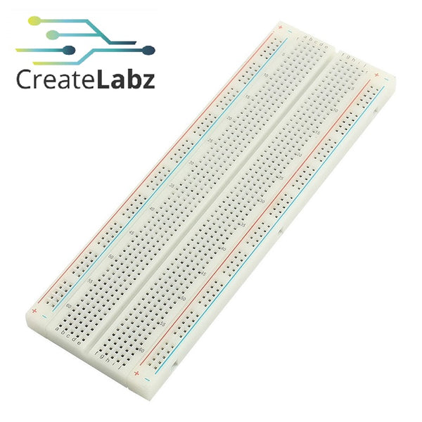
| Breadboard | Temporary platform for assembling and testing the circuit |
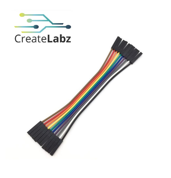
| Dupont Jumper Wires | Connect power, ground, and signal lines between components |
Software Tools
| Software | Details |
|---|---|
| Arduino IDE | Used to write and upload the ESP32-CAM firmware |
| Supabase | Cloud storage platform for captured images |
| Fritzing | Used to create the wiring diagram |
03 Application Discussion

ESP32-CAM is a small size camera development board based on ESP32, set WIFI+ Bluetooth solution in one body, the development board can work independently as a minimum system. and is perfect for IoT devices requiring a camera with advanced functions like image tracking and recognition.
Pinout:

How to upload code to ESP32 CAM using FTDI:

Application in this project:
The ESP32-CAM functions as the central controller in this system. It processes input from the motion sensor, captures images when activity/motion is detected, connects to a Wi-Fi network, and sends those images directly to a cloud database via Supabase. Its integrated camera module and wireless capabilities make it ideal for compact, smart surveillance applications without the need for external memory.
- PIR MOTION SENSOR
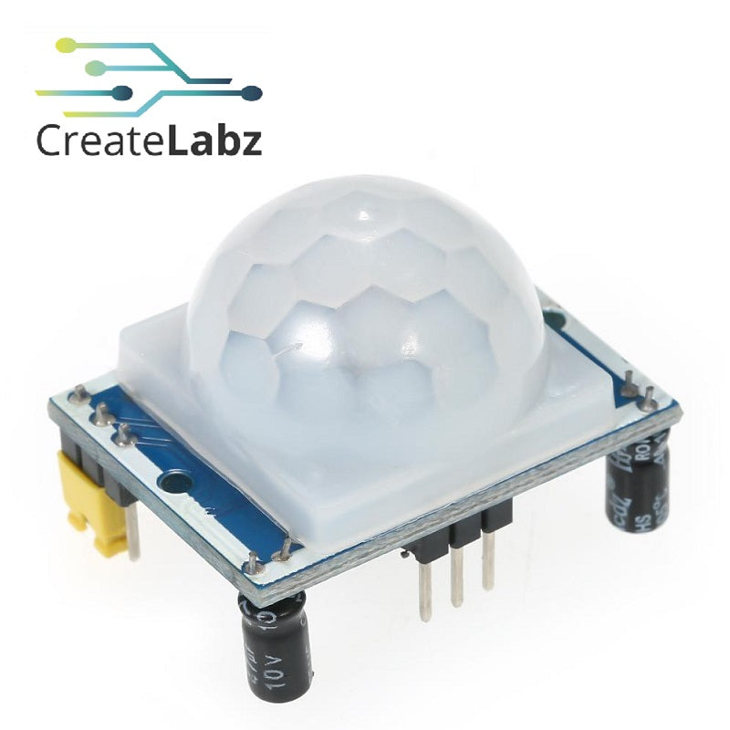
The PIR motion sensor acts as the system's trigger, constantly monitoring its surroundings for movement. When it detects changes in infrared radiation—typically caused by a person or object passing by—it sends a signal to the ESP32-CAM to initiate the photo capture process. Its ability to sense motion passively makes the setup power-efficient and event-driven, ensuring that the camera activates only when necessary.
Pinout:
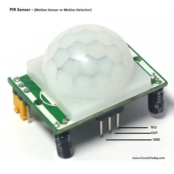
You can also open the FRESNEL LENS (the white cap) to check the labels/pinout of the PIR motion sensor.
Application in this project:
The PIR sensor is responsible for detecting motion in the environment. It identifies movement by sensing changes in infrared radiation and alerts the ESP32-CAM when something moves in its field of view. This sensor triggers the entire image capture process, making the system energy-efficient and responsive only when needed.
- FTDI PROGRAMMER
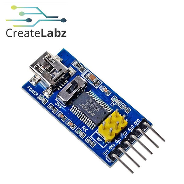
The FTDI cable plays a crucial role during the development and setup phase. It provides the necessary USB-to-serial communication link between the computer and the ESP32-CAM, allowing firmware uploads and real-time debugging via the serial monitor.
Pinout:
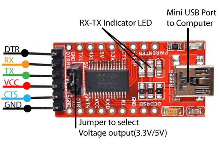
Application in this project:
The FTDI adapter is used to program the ESP32-CAM and establish serial communication with a computer. Since the ESP32-CAM doesn't have a built-in USB interface, this adapter bridges the connection for uploading code and performing serial monitoring during development and debugging.
- BREADBOARD
Application in this project:
The breadboard serves as a temporary platform for assembling and testing the circuit without soldering. It allows easy and flexible connections between components like the ESP32-CAM, PIR sensor, and power supply. During prototyping, the breadboard helps organize the wiring neatly and enables quick adjustments, making it ideal for experimenting and troubleshooting before finalizing the hardware setup.
- JUMPER WIRES
Application in this project:
Jumper wires are used to make electrical connections between components on the breadboard and the ESP32-CAM. They provide the necessary links for power, ground, and signal transmission between the PIR sensor, FTDI programmer, and other parts of the circuit. Their flexibility and reusability make them essential for prototyping and modifying circuits quickly and efficiently.
Supabase
- SUPABASE
Supabase is an open-source backend platform that makes it easy to store and manage data online—similar to tools like Firebase. It provides features like databases, authentication, file storage, and APIs so developers can build web and mobile apps faster.
In simple terms, Supabase acts like an online storage space or cloud service that your project can connect to using the internet.
Application in this project:
In this project, Supabase is used as the online storage platform where the ESP32-CAM sends images when motion is detected by the PIR sensor. Once the sensor is triggered, the ESP32-CAM captures a photo and connects to Wi-Fi to upload the image directly to a storage bucket on Supabase. This allows the system to save pictures remotely without needing an SD card or local memory. By using Supabase, users can easily access the captured images from any device connected to the internet, making the project function like a simple cloud-based surveillance system.
04 Hardware Setup
Wire the components as shown in the hardware diagram below.

ESP32-CAM and PIR Sensor
| Component Pin | ESP32-CAM Pin | Description |
|---|---|---|
| PIR signal | GPIO 13 | Digital motion trigger |
| PIR VCC | 5V | Powers the PIR sensor |
| PIR GND | GND | Common ground |
FTDI Programmer
| FTDI Pin | ESP32-CAM Pin | Purpose |
|---|---|---|
| VCC | 5V | Power |
| GND | GND | Common ground |
| TX | U0R | Serial transmit |
| RX | U0T | Serial receive |
Assembly Instructions
- Place the ESP32-CAM and PIR sensor on the breadboard.
- Connect the PIR signal to GPIO 13, plus VCC and GND.
- Connect the FTDI TX/RX lines to the ESP32-CAM serial pins.
- Connect GPIO 0 to GND only while uploading code, then disconnect it before running.
05 Software Setup
Install Arduino IDE, select the ESP32-CAM AI-Thinker board, configure the correct serial port, and create the Supabase storage bucket before uploading.
Board Settings
| Setting | Value |
|---|---|
| Board | AI Thinker ESP32-CAM |
| Upload speed | 115200 |
| Port | FTDI USB serial port |
Upload the Code
- Connect GPIO 0 to GND and connect the FTDI programmer.
- Upload the sketch from the Code section.
- Disconnect GPIO 0 from GND and reset the ESP32-CAM.
06 Code
Motion detection using ESP32-CAM with PIR motion sensor code:
#include "esp_camera.h"
#include <WiFi.h>
#include <HTTPClient.h>

const char* ssid = "GlobeAtHome_sample_only";
const char* password = "TzJgy3Yv";
const char* supabaseUrl = "https://uakfrdiqtxiwvfrqhoze.supabase.co";
const char* supabaseKey = "eyJhbGciOiJIUzI1NiIsInR5cCI6IkpXVCJ9.eyJpc3MiOiJzdXBhYmFzZSIsInJlZiI6InVha2ZyZGlxdHhpd3ZmcnFob3plIiwicm9sZSI6ImFub24iLCJpYXQiOjE3NTMxNjU3OTUsImV4cCI6MjA2ODc0MTc5NX0.7JKHGMDq8nMwXUwnA_Fy0HCwu3mOPWeUSeIwx_FJPq4";
const char* bucketName = "esp32synapseduo";

#define PIR_PIN 13
#define PWDN_GPIO_NUM 32
#define RESET_GPIO_NUM -1
#define XCLK_GPIO_NUM 0
#define SIOD_GPIO_NUM 26
#define SIOC_GPIO_NUM 27
#define Y9_GPIO_NUM 35
#define Y8_GPIO_NUM 34
#define Y7_GPIO_NUM 39
#define Y6_GPIO_NUM 36
#define Y5_GPIO_NUM 21
#define Y4_GPIO_NUM 19
#define Y3_GPIO_NUM 18
#define Y2_GPIO_NUM 5
#define VSYNC_GPIO_NUM 25
#define HREF_GPIO_NUM 23
#define PCLK_GPIO_NUM 22

void setupCamera() {
	camera_config_t config;
	config.ledc_channel = LEDC_CHANNEL_0;
	config.ledc_timer = LEDC_TIMER_0;
	config.pin_d0 = Y2_GPIO_NUM;
	config.pin_d1 = Y3_GPIO_NUM;
	config.pin_d2 = Y4_GPIO_NUM;
	config.pin_d3 = Y5_GPIO_NUM;
	config.pin_d4 = Y6_GPIO_NUM;
	config.pin_d5 = Y7_GPIO_NUM;
	config.pin_d6 = Y8_GPIO_NUM;
	config.pin_d7 = Y9_GPIO_NUM;
	config.pin_xclk = XCLK_GPIO_NUM;
	config.pin_pclk = PCLK_GPIO_NUM;
	config.pin_vsync = VSYNC_GPIO_NUM;
	config.pin_href = HREF_GPIO_NUM;
	config.pin_sscb_sda = SIOD_GPIO_NUM;
	config.pin_sscb_scl = SIOC_GPIO_NUM;
	config.pin_pwdn = PWDN_GPIO_NUM;
	config.pin_reset = RESET_GPIO_NUM;
	config.xclk_freq_hz = 20000000;
	config.pixel_format = PIXFORMAT_JPEG;
	config.frame_size = FRAMESIZE_VGA;
	config.jpeg_quality = 10;
	config.fb_count = 1;

	esp_err_t err = esp_camera_init(&config);
	if (err != ESP_OK) {
		Serial.printf("Camera init failed: 0x%x", err);
		return;
	}
}

void uploadImage(camera_fb_t* fb) {
	if (!fb) {
		Serial.println("No photo captured.");
		return;
	}
	HTTPClient http;
	String fileName = "esp32synapseduo/" + String(millis()) + ".jpg";
	String url = String(supabaseUrl) + "/storage/v1/object/" + fileName;
	Serial.print("Uploading to: ");
	Serial.println(url);
	http.begin(url);
	http.addHeader("apikey", supabaseKey);
	http.addHeader("Authorization", "Bearer " + String(supabaseKey));
	http.addHeader("Content-Type", "image/jpeg");
	int httpResponseCode = http.PUT(fb->buf, fb->len);
	Serial.print("Upload response: ");
	Serial.println(httpResponseCode);
	if (httpResponseCode == 200 || httpResponseCode == 201) {
		Serial.println("Upload successful!");
	} else {
		Serial.println("Upload failed. Check URL, headers, or bucket name.");
		Serial.println(http.getString());
	}
	http.end();
}

void setup() {
	Serial.begin(115200);
	pinMode(PIR_PIN, INPUT);
	WiFi.begin(ssid, password);
	while (WiFi.status() != WL_CONNECTED) {
		delay(500);
		Serial.print(".");
	}
	Serial.println("\nWiFi connected");
	setupCamera();
}

void loop() {
	if (digitalRead(PIR_PIN) == HIGH) {
		Serial.println("Motion detected!");
		camera_fb_t* fb = esp_camera_fb_get();
		if (!fb) {
			Serial.println("Camera capture failed");
			return;
		}
		uploadImage(fb);
		esp_camera_fb_return(fb);
		delay(10000); // avoid multiple triggers
	}
}
07 Code Breakdown
Libraries Used
#include "esp_camera.h"
#include <WiFi.h>
#include <HTTPClient.h>-
esp_camera.h: Handles camera initialization and image capture.
-
WiFi.h: Used to connect the ESP32-CAM to Wi-Fi.
-
HTTPClient.h: Used to make HTTP PUT requests to Supabase for uploading images.
WiFi Credentials
const char* ssid = "GlobeAtHome_sample_only";
const char* password = "TzJgy3Yv";
Your home Wi-Fi credentials. The ESP32-CAM connects to this network to access the internet.
Supabase Configuration
const char* supabaseUrl = "https://uakfrdiqtxiwvfrqhoze.supabase.co";
const char* supabaseKey = "eyJhbGci...";  // Anon key
const char* bucketName = "esp32synapseduo";-
supabaseUrl: Your Supabase project URL.
-
supabaseKey: The anon public key used to authenticate image uploads.
-
bucketName: The name of the Supabase Storage bucket where photos will be saved.
PIR Sensor Pin
#define PIR_PIN 13Connects the PIR sensor’s output to GPIO 13 on the ESP32-CAM.
ESP32-CAM Pin Definitions for AI-Thinker Board
#define PWDN_GPIO_NUM 32
#define RESET_GPIO_NUM -1
#define XCLK_GPIO_NUM 0
#define SIOD_GPIO_NUM 26
#define SIOC_GPIO_NUM 27
#define Y9_GPIO_NUM 35
#define Y8_GPIO_NUM 34
#define Y7_GPIO_NUM 39
#define Y6_GPIO_NUM 36
#define Y5_GPIO_NUM 21
#define Y4_GPIO_NUM 19
#define Y3_GPIO_NUM 18
#define Y2_GPIO_NUM 5
#define VSYNC_GPIO_NUM 25
#define HREF_GPIO_NUM 23
#define PCLK_GPIO_NUM 22
These define how the ESP32-CAM is wired to its internal camera module. This configuration is required for esp_camera_init() to work correctly.
setupCamera()
Initializes the camera with the correct configuration. If it fails, it prints an error.
uploadImage()
-
Constructs a unique filename using the millis() timestamp.
-
Creates the Supabase upload URL.
-
Sends the image as a PUT request to the cloud.
-
Prints HTTP response codes (e.g., 200 for success, 400/403 for errors).
setup()
-
Starts the Serial monitor.
-
Connects to Wi-Fi.
-
Initializes the camera.
loop()
-
Continuously checks if the PIR sensor is triggered.
-
If motion is detected:
-
Captures a photo from the camera buffer.
-
Uploads it to Supabase.
-
Returns the camera buffer to free memory.
-
Waits 10 seconds to prevent repeated triggers.
08 Testing and Calibration
After uploading, verify the Wi-Fi connection, motion trigger, camera capture, and Supabase upload.
Testing and Calibration:
- During testing, the ESP32-CAM was first connected to Wi-Fi to verify that the module could successfully join the network. The Serial Monitor confirmed a successful connection by displaying the IP address.
- Next, the PIR motion sensor was tested by moving in front of it at various distances. At first, the sensor triggered too frequently due to its sensitivity and ambient motion like fans. We repositioned it and ensured it faced a clear direction with minimal background movement.
- We then checked if the ESP32-CAM was capturing images properly after motion was detected. In some tests, no image was captured—this was fixed by making sure the camera was initialized correctly in the
setupCamera()function and the camera ribbon cable was fully seated. - Once the photo began uploading successfully, we verified in the Supabase dashboard that each image appeared with a unique name.
- Minor timing adjustments were also made, such as adding a 10-second delay after each capture to prevent constant triggering from one motion event.
Final Adjustments:
-
We made sure that all the jumper wires and breadboard connections were tightly secured and in the right places so the system wouldn’t randomly restart or stop working.
-
We double-checked the power supply to make sure it was enough for the ESP32-CAM, especially since both the camera and Wi-Fi need a lot of power to run properly.
-
The PIR motion sensor was adjusted so it wouldn’t trigger from things like moving curtains or electric fans. We positioned it where it could detect actual movement clearly.
-
We also checked the Supabase settings to make sure the image uploads were allowed and that we had permission to save and view files.
-
Lastly, we cleaned up the Serial Monitor messages to make the output easier to read when testing or troubleshooting.
Summary
-
PIR detects motion → ESP32-CAM captures image → Sends to Supabase cloud.
-
Fully self-contained IoT motion camera with remote image storage.
09 System Demonstration
10 Conclusion
The Smart Motion-Activated Camera System demonstrates an effective and accessible approach to home monitoring using low-cost hardware and cloud-based storage. By combining the ESP32-CAM with a PIR motion sensor and Supabase, the project creates a self-contained surveillance unit capable of detecting movement, capturing images, and storing them online—all without the need for local storage or expensive equipment.
This project not only provides a practical solution for basic security and automation tasks but also introduces users to key Internet of Things (IoT) concepts, including sensor integration, wireless connectivity, and cloud interaction. It’s ideal for beginners and hobbyists who want to explore real-world applications of embedded systems while building something useful and scalable.
Whether used for indoor monitoring, entryway surveillance, or as a foundation for more complex smart home systems, this motion-triggered photo logger serves as an excellent starting point for exploring DIY security and automation.
11 References
- Youtube: Pir Motion Sensor Detect Object & ESP32-CAM Takes A Photo And Automatic Saves It On The Microsd Card
- Arduino Official Website
- Espressif Systems
- Random Nerds Tutorial
- Github Community Examples
- Supabase Documentation
12 Project Authors
- Lenie Joy Badil
- Naphtali Montayre
- John Ronan M. Limbadan
- Alexander B. Maiso