

Overview
This mini-project covers the functionality of an ADXL345 Triple-Axis Accelerometer on an Arduino UNO board and uses Processing 3 to visualize the 3D animation control. The x, y, and z values obtained by the accelerometer will be transformed into a 3D object animation where it mimics the movements of an accelerometer. The Arduino UNO communication protocol used is the Inter-integrated Circuit (I2C) protocol.
Hardware Components
Software Components
Application Discussion
What is an ADXL345 Accelerometer and how does it work?
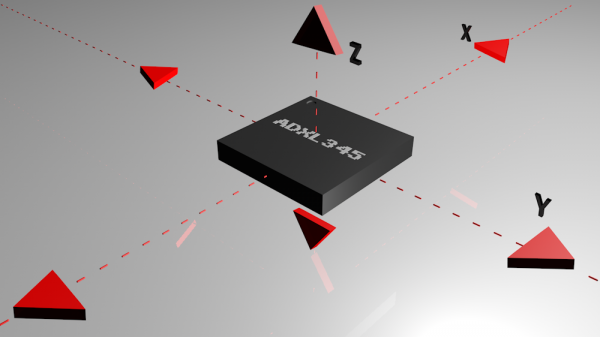
The ADXL345 is a small, thin, low power, 3-axis MEMS accelerometer with high resolution (13-bit) measurement at up to +/-16 g. Digital output data is formatted as 16-bit two’s complement and is accessible through either an SPI (3- or 4-wire) or I2C digital interface.
Accelerometers are devices that measure acceleration, which is the rate of change of the velocity of an object. They measure in meters per second squared (m/s2) or in G-forces (g). A single G-force here on planet Earth is equivalent to 9.8 m/s2, but this will vary due to elevation and gravitational pull variations. Accelerometers are useful for sensing vibrations in systems or for orientation applications.
They are electromechanical devices that sense either static (gravity) or dynamic (vibrations and movement) forces of acceleration.
Most of the accelerometers used today measure 3 axes since the cost of development for them decreases.
In general, accelerometers contain capacitive plates internally. Some of these are fixed, while others are attached to minuscule springs that move internally as acceleration forces act upon the sensor. As these plates move in relation to each other, the capacitance between them changes. The changes in capacitance determine the acceleration.
Other accelerometers can be centered around piezoelectric materials. These tiny crystal structures output electrical charge when placed under mechanical stress (e.g. acceleration).

An internal structure of a piezoelectric accelerometer
How To Connect to an Accelerometer (Communication Protocols)
Accelerometers will communicate over an analog, digital, or pulse-width modulated connection interface.
- Accelerometers with an analog interface show accelerations through varying voltage levels. These values generally fluctuate between ground and the supply voltage level. An ADC on a microcontroller can then be used to read this value. These are generally less expensive than digital accelerometers. This communication interface is more susceptible to noise.
- Accelerometers with a digital interface can either communicate over SPI or I2C communication protocols. These tend to have more functionality and be less susceptible to noise than analog accelerometers.
- Accelerometers that output data over pulse-width modulation (PWM) output square waves with a known period, but a duty cycle that varies with changes in acceleration. [1]
How To Power An Accelerometer?
Some triple-axis accelerometers have a logic level converter in their internal circuitry. You’ll know if it has an addition 3.3V pin beside the VCC pin. I used an accelerometer with no internal logic level converter so I have to use a separate one if I intend to use SPI protocol.
NOTE: If you plan on using the ADXL345 in I2C mode, you don’t need a Logic Level Converter since there are pull-up resistors to power up Arduino pins to 3.3V.
Technical Details (ADXL345)
- 2.0 – 3.6 VDC Supply Voltage
- Ultra Low Power: 40uA in measurement mode, 0.1uA in standby@ 2.5V
- Tap/Double Tap Detection
- Free-Fall Detection
- SPI and I2C interfaces
The last three details listed above are the additional features of the ADXL345 Triple-Axis Accelerometer. Tap sensing detects single and double taps in any direction. Freefall sensing detects if the device is falling. These functions can be mapped individually to either of two interrupt output pins. An integrated memory management system with a 32-level first in, first out (FIFO) buffer can be used to store data to minimize host processor activity and lower overall system power consumption.
Applications
- Handsets
- Medical Instrumentation
- Gaming and Pointing Devices
- Industrial Instrumentation
- Personal Navigation Devices
- Hard Disk Drive (HDD) protection
To further research about the functionality of an ADXL345 Triple-Axis Accelerometer, here is the link to the datasheet: ADXL345 datasheet
What is Processing 3?
![]()
Processing was initially created to serve as a software sketchbook and to teach programming fundamentals within a visual context, Processing has also evolved into a development tool for professionals. The Processing software is free, open source, and runs on the Mac, Windows, and GNU/Linux platforms. The Processing community has written more than a hundred libraries to facilitate computer vision, data visualization, music composition, networking, 3D file exporting, and programming electronics.
Processing is geared toward creating visual, interactive media, so the first programs start with drawing. Students new to programming find it incredibly satisfying to make something appear on their screen within moments of using the software. This motivating curriculum has proved successful for leading design, art, and architecture students into programming and for engaging the wider student body in general computer science classes. [5]
In this project, Processing 3 was used to visualize a 3D object that will be controlled by the accelerometer using Java language.
Set-up the Hardware

Before we can use the accelerometer, we have to calibrate it first to determine the stable reference force for both directions in each of the three axes.
Calibration Method
- Assemble the hardware components as shown above. Don’t place the accelerometer on the breadboard yet. You can also place the sensor on the breadboard but you will need a flat surface to stick the breadboard on it. Note that it won’t be as accurate if you place the sensor on a block of wood.
- Mount the sensor on a small box or a block of wood and place it on a firm, flat surface.

Photo Credit: Adafruit - Copy and upload the Arduino code below for the accelerometer calibration. Open the serial monitor and wait for the prompt.
- Position the block so that the arrow of the axis in the sensor is pointing upward (positive axis) or pointing downward (negative axis).
- Type any character on the serial monitor and hit return or press enter. The sketch will take a measurement of that axis and print the results.
- Repeat the steps 4 to 5 for the rest of the 5 sides. Your sample result for all six sides will look like this.

- Record the data for acceleration minimums and maximums in this way.

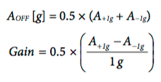
- To solve for the offset and gain, use the following equations as stated in the Application Note from Analog Devices (page 8: equations 17 and 18).
This is my sample table from the data obtained in the serial monitor above.

You will place the new values of the offset and gain in the DEFINED VARIABLES part of the code. It was initially set to 0 (for offset) and 1 (for gain).

Placing the new offset and gain values, the DEFINED VARIABLES will look like this.

You have to uncomment this part of the code so that you will see the new calibrated calues for x, y, and z.
 Now, if you re-do steps 3 to 5, the new calibrated values will look like this. The 0 0 1 on the first output below indicates that the z-axis has been calibrated to 1 g or 1 gravitational force. All x, y, z values must have a calibrated value of 1 before continuing to the next steps.
Hardware Assembly and Software
- Assemble the hardware components as shown above (either on the breadboard or still on the block of wood).
- Copy the Arduino code below and click the Upload button. You can verify if the accelerometer is working by clicking the serial monitor and observing if there are variations in the x, y, z
- Close the serial monitor so that the Processing 3 visuals will run.
- Copy the processing 3 code below and click the run button. You can now move your sensor and the 3D animation will mimic it.
NOTE: Make sure that the serial monitor is closed before clicking run on the Processing 3. make sure that the Processing 3 animation window is closed before opening the serial monitor.
Code
Libraries used (Arduino)
SparkFun_ADXL345.h Library by SparkFun
This library by SparkFun has all the ADXL345 features and functionalities defined in the Library. These are shown in pp 20-22 of the ADXL345 datasheet, which are the INTERRUPTS, DATA_READY, SINGLE_TAP, DOUBLE_TAP, FREE_FALL, and many more.
Wire.h by Arduino
This Library allows you to communicate with I2C/TWI devices. On the Arduino boards with the R3 layout (1.0 pinout), the SDA (data line) and SCL (clock line) are on the pin headers to close to the AREF pin. This library is already in the default libraries on the Arduino sketch tab. [2]
Libraries used (Processing 3)
processing.opengl.*
OpenGL (Open Graphics Library) is a cross-platform graphics interface for 3D and 2D graphics. This library allows Processing programs to utilize the speed of an OpenGL accelerated graphics card. This expands the potential for drawing more to the screen and creating larger windows. [3]
processing.serial.*
The Serial library reads and writes data to and from external devices one byte at a time. It allows two computers to send and receive data. This library has the flexibility to communicate with custom microcontroller devices and to use them as the input or output to Processing programs. The serial port is a nine pin I/O port that exists on many PCs and can be emulated through USB. [4]
Arduino code (sensor calibration)
/*  *****************************************
 *  ADXL345_Calibration
 *  ADXL345 Hook Up Guide Calibration Example
 *
 *  Utilizing Sparkfun's ADXL345 Library
 *  Bildr ADXL345 source file modified to support
 *  both I2C and SPI Communication
 *
 *  E.Robert @ SparkFun Electronics
 *  Created: Jul 13, 2016
 *  Updated: Sep 13, 2016
 *
 *  Development Environment Specifics:
 *  Arduino 1.6.11
 *
 *  Hardware Specifications:
 *  SparkFun ADXL345
 *  Arduino Uno
 *  *****************************************/

#include <SparkFun_ADXL345.h>

/*********** COMMUNICATION SELECTION ***********/
/*    Comment Out The One You Are Not Using    */
//ADXL345 adxl = ADXL345(10);           // USE FOR SPI COMMUNICATION, ADXL345(CS_PIN);
ADXL345 adxl = ADXL345();             // USE FOR I2C COMMUNICATION

/****************** VARIABLES ******************/
/*                                             */
int AccelMinX = 0;
int AccelMaxX = 0;
int AccelMinY = 0;
int AccelMaxY = 0;
int AccelMinZ = 0;
int AccelMaxZ = 0;

int accX = 0;
int accY = 0;
int accZ = 0;

/************** DEFINED VARIABLES **************/
/*                                             */
#define offsetX   0       // OFFSET values
#define offsetY   0
#define offsetZ   0

#define gainX     1        // GAIN factors
#define gainY     1
#define gainZ     1

/******************** SETUP ********************/
/*          Configure ADXL345 Settings         */
void setup()
{
  Serial.begin(9600);                 // Start the serial terminal
  Serial.println("SparkFun ADXL345 Accelerometer Breakout Calibration");
  Serial.println();

  adxl.powerOn();                     // Power on the ADXL345

  adxl.setRangeSetting(2);           // Give the range settings
                                      // Accepted values are 2g, 4g, 8g or 16g
                                      // Higher Values = Wider Measurement Range
                                      // Lower Values = Greater Sensitivity

  adxl.setSpiBit(0);                // Configure the device: 4 wire SPI mode = '0' or 3 wire SPI mode = 1
                                      // Default: Set to 1
                                      // SPI pins on the ATMega328: 11, 12 and 13 as reference in SPI Library
}

/****************** MAIN CODE ******************/
/*  Accelerometer Readings and Min/Max Values  */
void loop()
{
  Serial.println("Send any character to display values.");
  while (!Serial.available()){}       // Waiting for character to be sent to Serial
  Serial.println();

  // Get the Accelerometer Readings
  int x,y,z;                          // init variables hold results
  adxl.readAccel(&x, &y, &z);         // Read the accelerometer values and store in variables x,y,z

  if(x < AccelMinX) AccelMinX = x;
  if(x > AccelMaxX) AccelMaxX = x;

  if(y < AccelMinY) AccelMinY = y;
  if(y > AccelMaxY) AccelMaxY = y;

  if(z < AccelMinZ) AccelMinZ = z;
  if(z > AccelMaxZ) AccelMaxZ = z;

  Serial.print("Accel Minimums: "); Serial.print(AccelMinX); Serial.print("  ");Serial.print(AccelMinY); Serial.print("  "); Serial.print(AccelMinZ); Serial.println();
  Serial.print("Accel Maximums: "); Serial.print(AccelMaxX); Serial.print("  ");Serial.print(AccelMaxY); Serial.print("  "); Serial.print(AccelMaxZ); Serial.println();
  Serial.println();


  /* Note: Must perform offset and gain calculations prior to seeing updated results
  /  Refer to SparkFun ADXL345 Hook Up Guide: https://learn.sparkfun.com/tutorials/adxl345-hookup-guide
  /  offsetAxis = 0.5 * (Acel+1g + Accel-1g)
  /  gainAxis = 0.5 * ((Acel+1g - Accel-1g)/1g) */
  /*
  accX = (x - offsetX)/gainX;         // Calculating New Values for X, Y and Z
  accY = (y - offsetY)/gainY;
  accZ = (z - offsetZ)/gainZ;

  Serial.print("New Calibrated Values: ");
  Serial.print(accX); Serial.print("  "); Serial.print(accY); Serial.print("  "); Serial.print(accZ);
  Serial.println();
  */

  while (Serial.available())
  {
    Serial.read();                    // Clear buffer
  }
}
The code itself is already understandable with the aid of the comments beside the code functions.
Arduino code (ADXL345 to Arduino to Serial port) by Live Fast – Code Young
#include <Wire.h>

#define DEVICE (0x53)    //ADXL345 device address
#define TO_READ (6)        //num of bytes we are going to read each time (two bytes for each axis)

#define offsetX   -10.5       // place your OFFSET values here
#define offsetY   -2.5
#define offsetZ   -4.5

#define gainX     257.5        // place your GAIN factors
#define gainY     254.5
#define gainZ     248.5

byte buff[TO_READ] ;    //6 bytes buffer for saving data read from the device
char str[512];                      //string buffer to transform data before sending it to the serial port

void setup()
{
  Wire.begin();        // join i2c bus (address optional for master)
  Serial.begin(9600);  // start serial for output

  //Turning on the ADXL345
  writeTo(DEVICE, 0x2D, 0);
  writeTo(DEVICE, 0x2D, 16);
  writeTo(DEVICE, 0x2D, 8);
}

void loop()
{
  int regAddress = 0x32;    //first axis-acceleration-data register on the ADXL345
  int x, y, z;

  readFrom(DEVICE, regAddress, TO_READ, buff); //read the acceleration data from the ADXL345

   //each axis reading comes in 10 bit resolution, ie 2 bytes.  Least Significat Byte first!!
   //thus we are converting both bytes in to one int
  x = (((int)buff[1]) << 8) | buff[0];
  y = (((int)buff[3])<< 8) | buff[2];
  z = (((int)buff[5]) << 8) | buff[4];

  //we send the x y z values as a string to the serial port
  sprintf(str, "%d %d %d", x, y, z);
  Serial.print(str);
  Serial.print(10, byte());

  //It appears that delay is needed in order not to clog the port
  delay(100);
}

//---------------- Functions
//Writes val to address register on device
void writeTo(int device, byte address, byte val) {
   Wire.beginTransmission(device); //start transmission to device
   Wire.write(address);        // send register address
   Wire.write(val);        // send value to write
   Wire.endTransmission(); //end transmission
}

//reads num bytes starting from address register on device in to buff array
void readFrom(int device, byte address, int num, byte buff[]) {
  Wire.beginTransmission(device); //start transmission to device
  Wire.write(address);        //sends address to read from
  Wire.endTransmission(); //end transmission

  Wire.beginTransmission(device); //start transmission to device
  Wire.requestFrom(device, num);    // request 6 bytes from device

  int i = 0;
  while(Wire.available())    //device may send less than requested (abnormal)
  {
    buff[i] = Wire.read(); // receive a byte
    i++;
  }
  Wire.endTransmission(); //end transmission
}
Processing 3 code (3D Animation Control) by Live Fast – Code Young
import processing.opengl.*;
import processing.serial.*;

//Sets variables for serial port, bytes, and floats
Serial sp;
byte[] buff;
float[] r;

float OFFSET_X = 2.5, OFFSET_Y = -2.5;    //These offsets are chip specific, and vary.  Play with them to get the best ones for you

//This sets up the Processing 3 Java window dimension and visuals
void setup() {
  size(400, 300, P3D);
  sp = new Serial(this, "/dev/cu.wchusbserial1410",  9600); //You have to rename your port in the "" and change the baud rate.
  buff = new byte[128];
  r = new float[3];
}

float protz, protx;
void draw() {
  //perspective( 45, 4.0/3.0, 1, 5000 );
  translate(400/2, 300/2, -400); //Sets left/right, up/down, and toward/away translation
  background(0); //Sets background color to black
  buildShape(protz, protx); //Used to define a new shape

    int bytes = sp.readBytesUntil((byte)10, buff); //It will only read until 10 bytes of data
    String mystr = (new String(buff, 0, bytes)).trim(); //trim removes whitespace at start of string
    if(mystr.split(" ").length != 3) { //uses string to break characters by using a delimiter ""
      println(mystr);
      return;
    }
    setVals(r, mystr);

    float z = r[0], x = r[1];
    if(abs(protz - r[0]) < 0.05)
      z = protz;
     if(abs(protx - r[1]) < 0.05)
     x = protx;
    background(0);
    buildShape(z, x);

     protz = z;
     protx = x;
    println(r[0] + ", " + r[1] + ", " + r[2]); //prints x, y, z values in the console
}

//This sets up the 3D object inside the window
void buildShape(float rotz, float rotx) {
  pushMatrix();
  scale(6,6,14);
  rotateZ(rotz);
    rotateX(rotx);
    fill(255);
     stroke(0);
     box(60, 10, 10);
     fill(0, 255, 0);
     box(10, 9, 40);
     translate(0, -10, 20);
     fill(255, 0, 0);
     box(5, 12, 10);
  popMatrix();
}
//Sets the values in an array
void setVals(float[] r, String s) {
  int i = 0;
  r[0] = -(float)(Integer.parseInt(s.substring(0, i = s.indexOf(" "))) +OFFSET_X)*HALF_PI/256;
  r[1] = -(float)(Integer.parseInt(s.substring(i+1, i = s.indexOf(" ", i+1))) + OFFSET_Y)*HALF_PI/256;
  r[2] = (float) Integer.parseInt(s.substring(i+1));


}
Conclusion
There you have it! A fun project in using the ADXL345 accelerometer in controlling 3D objects. This project is usually used in gaming control and navigation devices. You now know the basics of gaming and navigation by using this sensor. You can also try experimenting it by adding a servo so that it will also mimic the sensor along the 3D animation on your computer screen.
References
[1] https://learn.sparkfun.com/tutorials/adxl345-hookup-guide
[2] https://www.arduino.cc/en/Reference/Wire
[3] https://github.com/processing/processing/wiki/OpenGL-Issues
[4] https://processing.org/reference/libraries/serial/index.html
[5] https://processing.org/overview/
The post 3D Animation of ADXL345 Triple-Axis Accelerometer on Arduino UNO and Processing 3 IDE appeared first on CreateLabz.


