
4-Wheel Drive Multifunction (Wireless) Robot Car Kit (1/2)
01 Overview
This is the first part of the 2-part project for the 4-wheel drive multifunction (wireless) robot car kit. The first part covers the functionality of a robot car with its own obstacle avoidance capability using both ultrasonic sensors and infrared obstacle avoidance modules. The robot car is completely autonomous to the robot car kit owner. The robot car uses the left-facing obstacle avoidance mechanism for simplicity. Whenever an obstacle is detected in either the ultrasonic sensor or the IR obstacle avoidance modules, the car will automatically face to the left and assess if there's still an obstacle ahead. The process repeats until no obstacle is detected.
Here's a sample gif of the robot car:
02 Hardware and Software Components
Gather everything below before you start. This is your checklist — names, models, and versions only.
Hardware Components
| Component | Description |
|---|---|
| Smart Robot Car Kit (Complete) | The whole 4-wheel drive multifunction (wireless) robot car kit — batteries not included. |
| Geared Motor x 4 | Drives the four wheels of the robot car. |
| High-Quality Car Tires x 4 | Wheels mounted on the geared motors for traction. |
| Motor-Fixed Pieces x 4 | Mount the geared motors onto the chassis. |
| Acrylic Plates (100 x 213 x 5mm) x 2 | Form the bottom and top chassis of the robot car. |
| L298N Motor Driver Board x 1 | Dual H-Bridge driver that controls the speed and direction of the motors. |
| Arduino Uno w/ USB Cable x 1 | Microcontroller board that runs the obstacle avoidance program. |
| Arduino Sensor Extension Board v4.0 x 1 | Expands the Arduino pins for easier sensor and module connections. |
| Servo Holder Kit x 1 | Mounts the SG90 servo and ultrasonic sensor at the front of the car. |
| SG90 Servo x 1 | Rotates the ultrasonic sensor while scanning the surroundings. |
| Ultrasonic Sensor Module x 1 | Measures the distance to obstacles ahead using sound waves. |
| TCRT5000 Tracing Modules (IR Obstacle Avoidance) x 2 | Detect nearby obstacles on the left and right sides using infrared reflection. |
| 6V (4 AA) Battery Holder x 1 | Powers the motors through the L298N motor driver. |
| 9V Battery Holder x 1 | Powers the Arduino Uno board. |
| Jumper Wires | Connect all the modules, sensors, and the Arduino Uno. |
| Screw Kit x 1 | Fastens the motors, plates, and pillars of the chassis. |
Software Tools
| Software | Version / Details |
|---|---|
| Arduino IDE | Used for writing and uploading the code to the Arduino Uno board. |
03 Application Discussion
Here is what each component does and why it is part of this project.
How Servo Motors Work (RC/Hobby Servo)
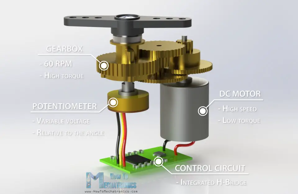
Inside a hobby servo motor, there's a gearbox, potentiometer, DC motor, and control circuit. As seen in the picture, the DC motor is high speed and low torque. Attached to it is the gearbox, which reduces the speed to 60 RPM and increases the torque.
The potentiometer and control circuit work together to compare the potentiometer voltage and the voltage coming from the signal line. The integrated H-Bridge in the controller enables the motor to rotate in either direction until two signals reach a difference of zero.
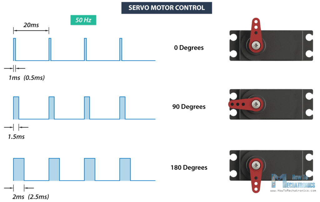
The angle of the servo motor is controlled by the different streams of pulses through the signal line. The frequency should be 50 Hz and pulses should occur every 20ms. 0 to 180-degree control varies from 0.5 ms to 2.5 ms pulse.
For more info about this servo, visit our store.
How Ultrasonic Sensors Work
Ultrasonic sensors are used to measure proximity by emitting and receiving sound waves. The trigger pin of the sensor enables the sound waves to be emitted from the sensor and unto the nearest object. The sound wave that is bounced back is then received by the echo, which calculates the travel time of the sound waves. The proximity is then measured through this mechanism.
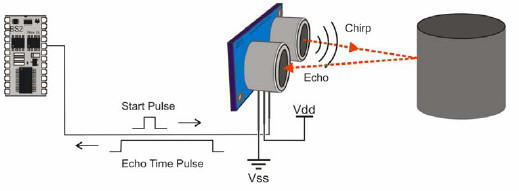
Photo Credit: hallroad.org
For more info about the technical details of ultrasonic sensors, visit our store.
How IR (Infrared) Obstacle Detectors Work
Infrared (IR) sensors are either passive or active sensors. Passive infrared sensors are basically infrared detectors or receivers. They detect radiation from an IR transmitter. IR receivers come in the form of photodiodes and phototransistors. Infrared photodiodes are different from normal photodiodes as they detect only infrared radiation.
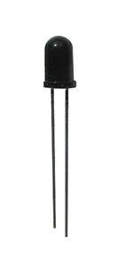
Photo Credit: Electronics Hub
An IR transmitter, which is an active IR sensor, is a light-emitting diode (LED) which emits infrared radiation. Although it looks like a normal LED, the light emitted is not visible to the naked eye. You can see the light through the camera of your smartphone.
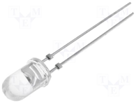
Photo Credit: Electronics Hub
The process of obstacle detecting is shown in the picture below. The rays reflected from the surface determine the distance of the object/body. In Arduino, the IR receiver only detects HIGH or LOW. HIGH means that there's no obstacle ahead or little-to-no ray is reflected to the receiver. LOW means that the object is near and/or there's a high amount of rays reflected or received by the IR receiver.
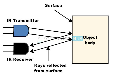
For more info about this IR obstacle detector, visit our shop.
How Does an L298N Motor Driver Module Work?
The L298N Motor Driver is actually essential in this project because it controls both the speed and direction of the motors with the use of dual H-Bridge motor control. The H-Bridge aids in the direction of control by "switching" or reversing the current flow. The switching elements are transistors or MOSFETs that open or close two at a time to change the rotation direction of the motor.
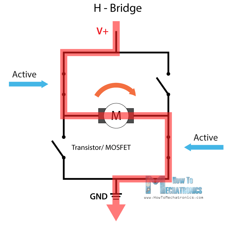
Since the L298N Motor Driver is a dual H-Bridge motor control, it can control the speed and direction of two motors. Let's take a look at the pin configurations of the module.
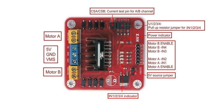
Photo Credit: Geeetech
There are two sets of yellow screw clamps for two motors. The middle screw clamps are for the VMS (to power up the module), GND, and 5V output to power other devices/boards such as the Arduino UNO board. However, the 5V output is not always used to supply voltage output. It can only be used if the input voltage (VMS) is up to 12V. In that way, the voltage regulator is activated, which also activates the 5V port as an output. But if the input voltage (VMS) is greater than 12V, we have to disconnect the jumper in the voltage regulator and make the 5V port as an input so that the IC will work properly and not be damaged.
The enable pins and input pins on the right corner of the picture are the connection between the Arduino and the module and to the motors. Input 1 and 2 control Motor A and Input 3 and 4 control Motor B. These input pins also control the switches in the H-bridge. If input 1 is LOW and input 2 is HIGH, the motor will move forward. It is the same for input 3 and 4, but it isn't always the case. You can also reverse the input wires in the screw clamps to change the direction of the motors.
04 Hardware Setup
Setting up the hardware is divided into two parts: setting up the bottom chassis and setting up the top chassis. Before setting up the smart robot car, you must prepare the hardware components needed. The list of materials is already stated in Section 02.
Setting up the Bottom Chassis
The first step is to solder the wires to the geared motors. Each geared motor has two wires — one for power (red) and one for ground (black). Solder a matching pair of wires securely to each of the four geared motors. Make sure the solder joints are solid and insulated, as loose connections will cause the motors to function intermittently.
Next, screw one geared motor into the indicated spot on the bottom acrylic plate. Repeat this step for the remaining three geared motors, placing them in their designated positions around the chassis. Each motor should be firmly secured with its mounting screws so that the wheels align properly and do not wobble during operation.
Attach the tires and steering gears to the geared motors. The tires should fit snugly over the motor shafts, and the steering gears must be aligned so that the wheels can pivot correctly. After attaching the tires and steering gears, screw the copper pillars and their corresponding screws onto the indicated spots on the bottom chassis. These pillars will support the top chassis and provide mounting points for the electronics.
Each side (left and right motors) should have one wire for the power source and one for ground. Twist the red wires together on each side and the black wires together on each side to create combined power and ground leads. This grouping simplifies the wiring and reduces clutter on the chassis.
Now, screw in place the infrared obstacle avoidance modules on the front-facing side of the bottom chassis. Position them so they face forward and have a clear line of sight for obstacle detection. Secure them firmly with their mounting hardware.
Once all motors, tires, steering gears, copper pillars, screws, and IR modules are installed and the wires are properly twisted and arranged, the bottom chassis assembly is complete. The bottom chassis should now have four geared motors with tires, four pairs of wired connections, two IR obstacle avoidance modules on the front, and the copper pillar mount points ready to support the top chassis.
Setting up the Top Chassis
The top chassis holds all the electronics — the Arduino Uno board, the L298N motor driver, the 9V battery holder, the servo holder with SG90 servo and ultrasonic sensor, and the Arduino Sensor Extension Board v4.0. The wiring diagram below shows how everything connects together.
Things to note about the top chassis:
- The wires for the battery case should follow the convention as seen in the wiring diagram. The red wire from the battery holder goes to the VMS / power source port of the L298N Motor Driver. The black wire from the battery holder should be twisted together with the GND wire from the Arduino Uno and connected to the GND port of the L298N Motor Driver.
- If your motor driver does not have labels (positive and negative) for the motor ports, you can arrange the motor wires as shown. If the tires are rotating in the opposite direction, you may switch the red and black wires of the motor until it rotates in the correct direction.
- You may use the different holes in the top chassis to make the wires from the bottom chassis (i.e., the IR Obstacle Avoidance Module to the Arduino) pass through cleanly, keeping the wiring organized and out of the way of moving parts.
Arrange the components on the top chassis so that the servo and ultrasonic sensor are positioned at the front of the car. Also consider space maximization and wire organization — you want your devices close enough to each other that you do not need excessively long wires, but arranged neatly so nothing obstructs the movement of the wheels or the rotation of the servo.
05 Software Setup
Open the Arduino IDE and upload the code on the Arduino Uno Board. The Servo.h library used in the code is a built-in library, so no additional installation is needed.
06 Code
Copy the code below into your Arduino sketch. Read the Code Breakdown section to understand what each part does.
Library Included
Servo.h by Arduino. This library is a default library in your Arduino IDE — no need to download it. This library allows the Arduino board to control servo motors. Standard servos allow the shaft to be positioned at various angles, usually between 0 and 180 degrees. Continuous rotation servos allow the rotation of the shaft to be set to various speeds.
Arduino Code
A big thanks to Chen the Design Maker for letting us use his Arduino code for this project. Some parts were edited since the robot turns left-facing when there's an obstacle ahead.
#include <Servo.h>

// Pins
#define TRIG_PIN 9
#define ECHO_PIN 10

//Define all the connections maps to the L298N
#define enA 13
#define in1 12
#define in2 11
#define in3 7
#define in4 6
#define enB 5
#define servoPin 2

//IR avoidance module
#define IRleft 4
#define IRright 8

class Motor {

    int enablePin;
    int directionPin1;
    int directionPin2;

  public:

    //Method to define the motor pins
    Motor(int ENPin, int dPin1, int dPin2) {
      enablePin = ENPin;
      directionPin1 = dPin1;
      directionPin2 = dPin2;
    };

    //Method to drive the motor 0~255 driving forward. -1~-255 driving backward
    void Drive(int speed) {
      if (speed >= 0) {
        digitalWrite(directionPin1, LOW);
        digitalWrite(directionPin2, HIGH);
      }
      else {
        digitalWrite(directionPin1, HIGH);
        digitalWrite(directionPin2, LOW);
        speed = - speed;
      }
      analogWrite(enablePin, speed);
    }
};

Motor leftMotor = Motor(enA, in1, in2);
Motor rightMotor = Motor(enB, in3, in4);
Servo myservo; // create servo object to control a servo

void motorInitiation() {
  pinMode(enA, OUTPUT);
  pinMode(in1, OUTPUT);
  pinMode(in2, OUTPUT);
  pinMode(enB, OUTPUT);
  pinMode(in3, OUTPUT);
  pinMode(in4, OUTPUT);
  // Set initial direction and speed
  digitalWrite(enA, LOW);
  digitalWrite(enB, LOW);
  digitalWrite(in1, LOW);
  digitalWrite(in2, HIGH);
  digitalWrite(in3, LOW);
  digitalWrite(in4, HIGH);
}

//Variables--------------------------------------------------------------------------
// Anything over 400 cm (23200 us pulse) is "out of range"
const unsigned int MAX_DIST = 23200;
bool USObstacle = false; //ultrasonic sensor obstacle
bool IRObstacleL = false; //left infrared sensor obstacle
bool IRObstacleR = false; //right infrared sensor obstacle
int servoPos = 90;

//IR variables
int isObstacleL = HIGH;  // HIGH MEANS NO OBSTACLE ON LEFT SIDE
int isObstacleR = HIGH;  // HIGH MEANS NO OBSTACLE ON RIGHT SIDE

enum Directions { Forward, TurnLeft, TurnRight, TurnAround, Brake};

Directions nextStep = Forward;

unsigned long t1;
unsigned long t2;
unsigned long pulse_width;
float cm;
float inches;

//SETUP--------------------------------------------------------------------------
void setup() {

  // The Trigger pin will tell the sensor to range find
  pinMode(TRIG_PIN, OUTPUT);
  digitalWrite(TRIG_PIN, LOW);

  //IR pins
  pinMode(IRleft, INPUT);
  pinMode(IRright, INPUT);

  // We'll use the serial monitor to view the sensor output
  Serial.begin(9600);
  myservo.attach(servoPin);
  motorInitiation();
  Directions nextStep = Forward;
}

void loop() {
  IRObstacleL = false;
  IRObstacleR = false;
  USObstacle = false;

  checkDistance();
  checkDirection();
  drive();
}

void checkDistance() {

  // Hold the trigger pin high for at least 10 us
  digitalWrite(TRIG_PIN, HIGH);
  delayMicroseconds(10);
  digitalWrite(TRIG_PIN, LOW);

  // Wait for pulse on echo pin
  while ( digitalRead(ECHO_PIN) == 0 );

  // Measure how long the echo pin was held high (pulse width)
  // Note: the micros() counter will overflow after ~70 min
  t1 = micros();
  while ( digitalRead(ECHO_PIN) == 1);
  t2 = micros();
  pulse_width = t2 - t1;

  // Calculate distance in centimeters and inches. The constants
  // are found in the datasheet, and calculated from the assumed speed
  //of sound in air at sea level (~340 m/s).
  cm = pulse_width / 58.0;
  inches = pulse_width / 148.0;
  Serial.println(pulse_width);

  //IR digital read
  isObstacleL = digitalRead(IRleft);
  isObstacleR = digitalRead(IRright);

  // Print out results
  if ( pulse_width > MAX_DIST ) {
    Serial.println("Out of range");
  } else {
    Serial.print(cm);
    Serial.print(" cm \\t");
    Serial.print(inches);
    Serial.println(" in");
  }

  // Wait at least 60ms before next measurement
  delay(60);

  if (cm <= 30) {
    USObstacle = true;
    Serial.println("Problem Ahead");

  }
  else {
    USObstacle = false;
  }

  //IR if-else statements
  if (isObstacleL == LOW && isObstacleR == HIGH) {
    IRObstacleL = true;
    IRObstacleR = false;
    Serial.println("Obstacle on left side");
  }
  else if (isObstacleR == LOW && isObstacleL == HIGH) {
    IRObstacleR = true;
    IRObstacleL = false;
    Serial.println("Obstacle on right side");
  }
  else if (isObstacleR == LOW && isObstacleL == LOW) {
    IRObstacleR = true;
    IRObstacleL = true;
    Serial.println("Obstacle on both sides");
  }
  else {
    IRObstacleL = false;
    IRObstacleR = false;
  }
}

void checkDirection() {
  Serial.println("checking direction");

  //the while loop will only exit when there's no obstacle detected by the sensors
  while ((IRObstacleL == true || IRObstacleR == true) || USObstacle == true) {
    Serial.println("Obstacle detected.");
    nextStep = Brake;
    drive();
    delay(300);
    nextStep = TurnLeft;
    drive();
    delay(200);
    nextStep = Brake;
    drive();
    delay(100);
    checkDistance(); //check if there's still an obstacle ahead
  }
  nextStep = Forward;
  drive();
}

void drive() {
  switch (nextStep) {
    case Forward:
      leftMotor.Drive(255);
      rightMotor.Drive(255);
      Serial.println("Forward");
      break;

    case TurnLeft:
      leftMotor.Drive(255);
      rightMotor.Drive(-255);
      Serial.println(" TurnLeft");
      delay(200);
      break;

    case Brake:
      leftMotor.Drive(0);
      rightMotor.Drive(0);
      Serial.println(" stopped");
  }

}
07 Code Breakdown
Here is what each part of the code does. Read this after uploading.
Library
| Library | Purpose |
|---|---|
| Servo.h | A default Arduino library that allows the board to control servo motors. Standard servos allow the shaft to be positioned at various angles, usually between 0 and 180 degrees. Continuous rotation servos allow the rotation of the shaft to be set to various speeds. |
Key Functions
class Motor
A custom class that groups the enable and direction pins of one side of the robot car. Its Drive(speed) method sets the direction pins for forward or backward rotation and drives the motor through analogWrite() with speeds from 0 to 255 forward and -1 to -255 backward.
motorInitiation()
Sets all the L298N motor pins as OUTPUT and applies the initial direction and speed states so the motors are ready to be driven.
setup()
Configures the ultrasonic trigger pin, sets the left and right IR pins as inputs, starts the serial monitor at 9600 baud, attaches the servo to its pin, and initiates the motors.
loop()
Resets the obstacle flags, then repeatedly runs checkDistance(), checkDirection(), and drive() to sense obstacles and react.
checkDistance()
Fires a 10-microsecond trigger pulse, measures the echo pulse width, converts it to centimeters and inches, and prints the readings to the serial monitor. It also digitally reads the left and right IR modules and updates the USObstacle, IRObstacleL, and IRObstacleR flags: the ultrasonic sensor flags an obstacle when the distance is 30 cm or less, while an IR module flags one when its reading is LOW.
checkDirection()
The left-facing obstacle avoidance logic. While any obstacle is detected, the car brakes, turns left, brakes again, and re-checks the distance until the path ahead is clear, after which it drives forward.
drive()
Executes the movement based on the nextStep state: Forward drives both motors at full speed, TurnLeft reverses the right motor to pivot the car left, and Brake stops both motors.
General Program Workflow
- Initialize the trigger pin, IR pins, serial monitor, servo, and motors in
setup(). - Reset the ultrasonic and IR obstacle flags.
- Measure the distance ahead and read the left and right IR modules.
- If an obstacle is detected, brake, turn left, brake, and re-check until the path is clear.
- Drive forward when no obstacle is detected.
- Repeat every loop cycle.
08 Testing and Output
Here is the video output of the robot car avoiding obstacles on its own.
Video Demonstration
10 Conclusion
There you have it! You can now play with your robot car. You can add more sensors to your car to add more functionality to it. You can also change the obstacle detection method of your robot.
11 References
- How Servo Motors Work & How to Control Servos using Arduino – HowToMechatronics — https://howtomechatronics.com/how-it-works/how-servo-motors-work-how-to-control-servos-using-arduino/
- IR Sensor Working Principle – Electronics Hub — https://www.electronicshub.org/ir-sensor/
12 Project Authors
- Eddyson Canoy
- John Ronan M. Limbadan
- Alexander B. Maiso