

Overview
This is the second part of the 2-part project for the 4-wheel drive multifunction (wireless) robot car kit. The first part was about a smart robot car that has its own obstacle detecting mechanism without the aid of user control. The second part covers the smart robot car controlled by an Android smartphone with the use of Bluetooth to communicate between the two devices.
Here’s a short gif of the test run:

Hardware Components
The whole smart robot car kit (batteries not included)
The components used in the kit:
Software Components
Application Discussion
How does a Bluetooth Module work?
The module that we will use is an HC-05 Bluetooth Module, which is an easy-to-use Bluetooth SPP (Serial Port Protocol) Module. It is designed for transparent wireless serial connection setup, which uses a MASTER-SLAVE configuration. This serial port Bluetooth module is fully qualified Bluetooth V2.0+EDR (Enhanced Data Rate) 3Mbps Modulation with complete 2.4GHz radio transceiver and baseband. It uses CSR Bluecore 04‐External single chip Bluetooth system with CMOS technology and with AFH (Adaptive Frequency Hopping Feature).

Technical Details (HC-05 Bluetooth Module)
Hardware Features
- Typical -80dBm sensitivity
- Up to +4dBm RF transmit power
- Low Power 1.8V Operation, 1.8 to 3.6V I/O
- PIO control
- UART interface with programmable baud rate
- With integrated antenna
- With edge connector
Software Features
- Default Baud rate: 38400, Data bits:8, Stop bit:1, Parity: No parity, Data control: has.
Supported baud rate: 9600, 19200, 38400, 57600, 115200, 230400, and 460800.
- Given a rising pulse in PIO0, the device will be disconnected.
- Status instruction port PIO1: low-disconnected, high-connected;
- PIO10 and PIO11 can be connected to red and blue led separately. When master and slave
are paired, red and blue led blinks 1time/2s in the interval, while disconnected only blue led blinks 2times/s.
- Auto-connect to the last device on power as default.
- Permit pairing device to connect as default.
- Auto-pairing PINCODE:”0000” as default
- Auto-reconnect in 30 min when disconnected as a result of beyond the range of connection. [3]
How does an L298N Motor Driver module work?
The L298N Motor Driver is actually essential in this project because it controls both the speed and direction of the motors with the use of dual H-Bridge motor control. The H-Bridge aids in the direction of control by “switching” or reversing the current flow. The switching elements are transistors or MOSFETs that open or close two at a time to change the rotation direction of the motor.
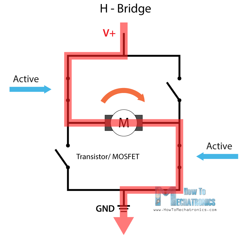
Since the L298N Motor Driver is a dual H-Bridge motor control, it can control the speed and direction of two motors. Let’s take a look at the pin configurations of the module.
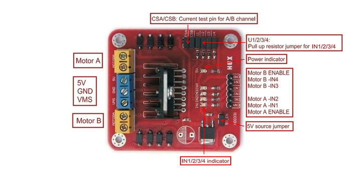
There are two sets of yellow screw clamps for two motors. The middle screw clamps are for the VMS (to power up the module), GND, and 5V output to power other devices/boards such as the Arduino UNO board. However, the 5V output is not always used to supply voltage output. It can only be used if the input voltage (VMS) is up to 12V. In that way, the voltage regulator is activated, which also activates the 5V port as an output. But if the input voltage (VMS) is greater than 12V, we have to disconnect the jumper in the voltage regulator and make the 5V port as an input so that the IC will work properly and not be damaged.
The enable pins and input pins on the right corner of the picture are the connection between the Arduino and the module and to the motors. Input 1 and 2 control Motor A and Input 3 and 4 control Motor B. This input pins also control the switches in the H-bridge. If input 1 is LOW and input 2 is HIGH, the motor will move forward. It is the same for input 3 and 4, but it isn’t always the case. You can also reverse the input wires in the screw clamps to change the direction of the motors.
What is MIT App Inventor 2?
 MIT App Inventor is an open-source web application provided by Google and is now maintained by the Massachusetts Institute of Technology. This web-based app helps you design Android apps in a fun and easy way. No need for typing a lot of codes since they have blocks, which can be interconnected to form a syntax.
Set-up the Hardware and Software
Setting up the hardware is divided into 2 parts: setting up the bottom chassis, top chassis, and Android app.
Before setting up the smart robot car, you must prepare the hardware components needed. The list of materials is already stated above.
Setting up the bottom chassis
The first thing to do is to solder the wires to the geared motors like the sample photo below.

Then, screw one geared motor to the indicated spot in the photo with these materials. Repeat this step to the other 3 geared motors.


Attach the tires and steering gears to the geared motors. After that, screw the following copper pillars and screws on the indicated spots on the bottom chassis.


Your output should look like this.

Each side (left and right motors) should have one wire for power source and ground. You have to wind or twist both red wires and black wires on each side.
Note: The color of the wires on top of the geared motor should not be the same since the motors are placed facing each other. 
Setting up the top chassis

The top chassis constitutes the following devices shown in the picture above (except for the geared motors).
Things to note about the top chassis:
- The wires for the battery case should follow the convention as seen in the picture above. Red wire goes to the VMS/power source port of the L295N Motor Driver. The black wire should be wind with the GND wire from the Arduino to the GND port of the L295N Motor Driver.
- If your motor driver doesn’t have labels (positive and negative) for the motor ports, you can arrange it like this. If the tires are rotating in the opposite direction, you may switch the red and black wires of the motor until it rotates in the correct direction.

Here’s a picture of the arrangement of my top chassis. You can arrange it however you want. The front part is the one where the Arduino is facing. Also, space maximization and wire organization are also things to consider when arranging your top chassis. You don’t want your devices to far from each other that you use longer wires.


Setting up Android app
Once all the hardware is in place, copy and run the Arduino code below.
In your smartphone, turn on your Bluetooth and find the HC-05 device, which is your Bluetooth module. Pair that device and it will ask for a pin for it to complete the pairing process. The pin is either 1234 or 0000.
Download the .apk file of the Android app here.

Here’s a screenshot of the Android application.
Connect to the Bluetooth module first before controlling the robot car by clicking the “Connect to Bluetooth Device” button. After that, it will show all your paired and available Bluetooth devices nearby. Find and click HC-05.
Before you connected to the Bluetooth module, the LED was blinking fast. You will know if you’ve connected your app to the module if the LED is now slowly blinking. If that happens, you can now play with the motor controls in the app.
The car speed buttons will change the motor speed of the car. Before clicking either of them, the default speed is the “Fast speed”.
Code
Library included
SoftwareSerial.h by Arduino
Software Serial is a default library in Arduino IDE. Just go to Sketch and include that Library. Although Arduino already has default Rx and Tx pins, you can assign other pins as Rx and Tx pins to use serial communication using this library. Keep in mind that this library only supports the digital pins of your Arduino board. In this project, I used digital pins 3 and 2 as Rx and Tx pins. The data sent by the Android app will be received by the Rx pin (digital pin 3) and it will relay that data to the Arduino through the Tx pin (digital pin 2).
Arduino code
#include <SoftwareSerial.h>

//Define all the connections maps to the L298N
#define enA 11
#define in1 12
#define in2 13
#define in3 7
#define in4 6
#define enB 5

class Motor {

    int enablePin;
    int directionPin1;
    int directionPin2;

  public:

    //Method to define the motor pins
    Motor(int ENPin, int dPin1, int dPin2) {
      enablePin = ENPin;
      directionPin1 = dPin1;
      directionPin2 = dPin2;
    };

    //Method to drive the motor 0~255 driving forward. -1~-255 driving backward
    void Drive(int speed) {
      if (speed >= 0) {
        digitalWrite(directionPin1, LOW);
        digitalWrite(directionPin2, HIGH);
      }
      else {
        digitalWrite(directionPin1, HIGH);
        digitalWrite(directionPin2, LOW);
        speed = - speed;
      }
      analogWrite(enablePin, speed);
    }
};

Motor leftMotor = Motor(enA, in1, in2);
Motor rightMotor = Motor(enB, in3, in4);

void motorInitiation() {
  pinMode(enA, OUTPUT);
  pinMode(in1, OUTPUT);
  pinMode(in2, OUTPUT);
  pinMode(enB, OUTPUT);
  pinMode(in3, OUTPUT);
  pinMode(in4, OUTPUT);
  // Set initial direction and speed
  digitalWrite(in1, LOW);
  digitalWrite(in2, HIGH);
  digitalWrite(in3, LOW);
  digitalWrite(in4, HIGH);
}

//Variables--------------------------------------------------------------------------
enum Directions { Forward, Reverse, TurnLeft, TurnRight, TurnAroundLeft, TurnAroundRight, Brake};
Directions nextStep = Forward;

SoftwareSerial BT(2, 3); //(tx pin, rx pin)

const byte numChars = 32;
char receivedChars[numChars];
String inputString = "";
boolean newData = false;
int carSpeed;
int carDelay1;
int carDelay2;

//SETUP--------------------------------------------------------------------------
void setup() {
  // We'll use the serial monitor to view the sensor output
  Serial.begin(9600);
  motorInitiation();

  BT.begin(9600);
  carSpeed = 255;
}

void loop() {

  receiveData();
  showNewData();
  androidCommand();
  drive();
  nextStep = Brake;
  drive();
  inputString = "";
}
/*this part here receives the data from the android app and stores it in a character array
 it has a mechanism that will prevent flooding of incoming strings if you've repeatedly
 clicked the button or clicked the button too fast*/

void receiveData() {
  static boolean recvInProgress = false;
  static byte ndx = 0;
  char startMarker = '<';
  char endMarker = '>';
  char rc;

  while (BT.available() > 0 && newData == false) {
    rc = BT.read();

    if (recvInProgress == true) {
      if (rc != endMarker) {
        receivedChars[ndx] = rc;
        ndx++;
        if (ndx >= numChars) {
          ndx = numChars - 1;
        }
      }
      else {
        receivedChars[ndx] = '\0'; // terminate the string
        recvInProgress = false;
        ndx = 0;
        newData = true;
      }
    }
    else if (rc == startMarker) {
      recvInProgress = true;
    }
  }
}

//shows the string received and reverts boolean to false if string is received
void showNewData() {
  if (newData == true) {
    inputString = String(receivedChars);
    Serial.println(inputString);
    newData = false;
  }
}

//this now translates the strings into motor speeds and directions
void androidCommand() {
  if (inputString == "forward"){
    nextStep = Forward;
}
  else if (inputString == "stop"){
    nextStep = Brake;
  }

  else if (inputString == "left"){
    nextStep = TurnLeft;
  }

  else if (inputString == "right"){
    nextStep = TurnRight;
  }

  else if (inputString == "reverse"){
    nextStep = Reverse;
  }

  else if (inputString == "uturnleft"){
    nextStep = TurnAroundLeft;
  }

  else if (inputString == "uturnright"){
    nextStep = TurnAroundRight;
  }

  else if (inputString == "slow"){
    carSpeed = 100;
    carDelay1 = 600;
    carDelay2 = 1100;
  }

  else if (inputString == "fast"){
    carSpeed = 255;
    carDelay1 = 200;
    carDelay2 = 400;
  }
}

//a case statement that shows all the motor directions
void drive() {
  switch (nextStep) {
    case Forward:
      leftMotor.Drive(carSpeed);
      rightMotor.Drive(carSpeed);
      Serial.println("Forward");
      delay(carDelay1);
      break;

    case Reverse:
      leftMotor.Drive(-carSpeed);
      rightMotor.Drive(-carSpeed);
      Serial.println("Reverse");
      delay(carDelay1);
      break;

    case TurnLeft:
      leftMotor.Drive(carSpeed);
      rightMotor.Drive(-carSpeed);
      Serial.println(" TurnLeft");
      delay(carDelay1);
      break;

    case TurnRight:
      leftMotor.Drive(-carSpeed);
      rightMotor.Drive(carSpeed);
      Serial.println(" TurnRight");
      delay(carDelay1);
      break;

    case TurnAroundLeft:
      leftMotor.Drive(carSpeed);
      rightMotor.Drive(-carSpeed);
      Serial.println(" TurnAroundLeft");
      delay(carDelay2);
      break;

    case TurnAroundRight:
      leftMotor.Drive(-carSpeed);
      rightMotor.Drive(carSpeed);
      Serial.println(" TurnAroundRight");
      delay(carDelay2);
      break;

    case Brake:
      leftMotor.Drive(0);
      rightMotor.Drive(0);
      Serial.println(" stopped");
      break;
  }

}
Conclusion
There you have it! A simple and fun way of controlling your smart robot car using your Android phone.
References
[1] https://learn.adafruit.com/introduction-to-bluetooth-low-energy/introduction
[2] https://www.link-labs.com/blog/bluetooth-vs-bluetooth-low-energy
[3] https://www.itead.cc/wiki/Serial_Port_Bluetooth_Module_(Master/Slave)_:_HC-05
The post (2/2) Android Phone-Controlled 4-Wheel Drive Multifunction (Wireless) Robot Car Kit appeared first on CreateLabz.


